To ensure fail-safe operation, the bus is to be biased at one end using the pull-up
and pull-down resistors on the communication module. In the 4-wire connection,
the pull-up and pull-down resistors are selected by setting jumpers X5, X6, X8, X9
to enabled position. The bus termination is selected by setting jumpers X7, X11 to
enabled position.
The jumpers have been set to no termination and no biasing as default.
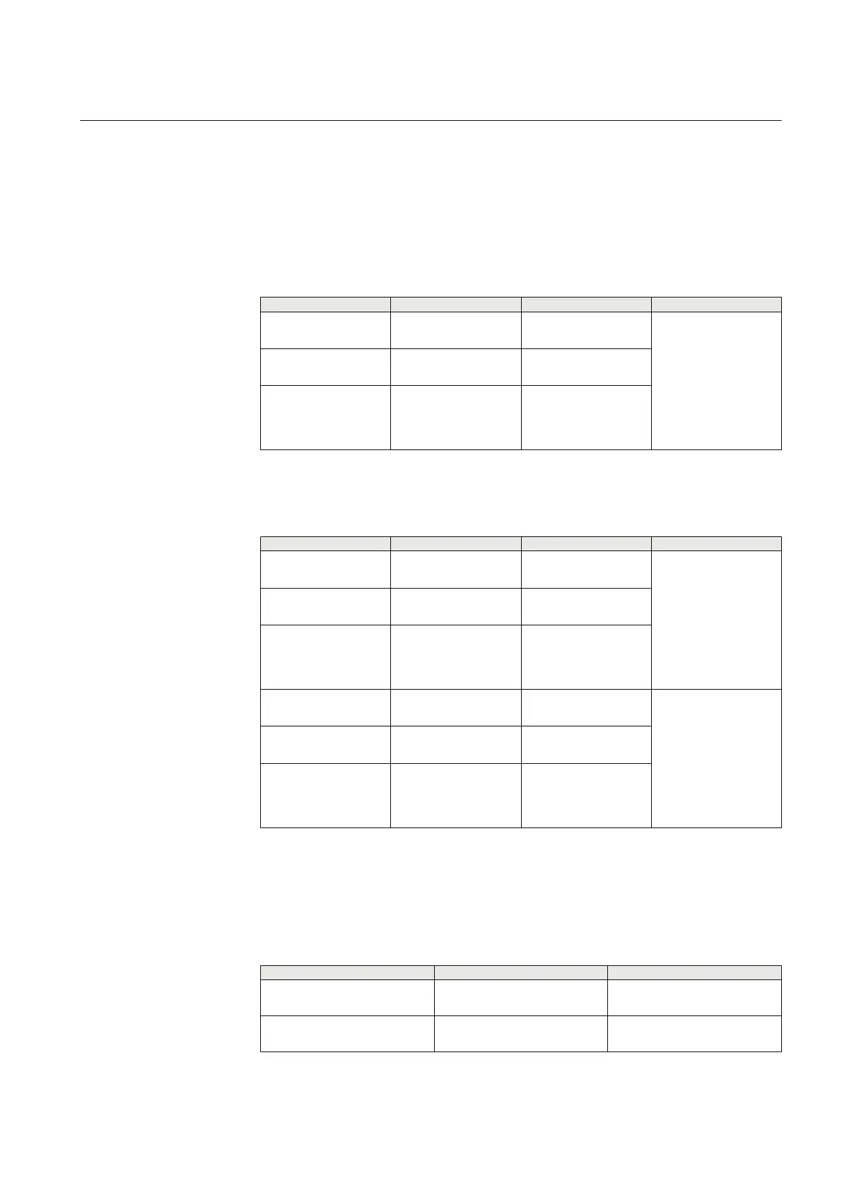
Table 675: 2-wire EIA-485 jumper connectors for COM1
Group Jumper connection Description Notes
X5 1-2
2-3
A+ bias enabled
A+ bias disabled
1)
COM1
Rear connector X6
2-wire connection
X6 1-2
2-3
B- bias enabled
B- bias disabled
1)
X7 1-2
2-3
Bus termination
enabled
Bus termination
disabled
1)
1) Default setting
Table 676: 4–wire EIA-485 jumper connectors for COM1
Group
Jumper connection Description Notes
X5 1-2
2-3
A+ bias enabled
A+ bias disabled
1)
COM1
Rear connector X6
4-wire TX channel
X6 1-2
2-3
B- bias enabled
B- bias disabled
1)
X7 1-2
2-3
Bus termination
enabled
Bus termination
disabled
1)
X9 1-2
2-3
A+ bias enabled
A+ bias disabled
1)
4-wire RX channel
X8 1-2
2-3
B- bias enabled
B- bias disabled
1)
X11 1-2
2-3
Bus termination
enabled
Bus termination
disabled
1)
1) Default setting
COM2 port connection can be either EIA-485 or optical ST. Connection type is
selected by setting jumpers X27 and X28.
Table 677: COM2 serial connection X5 EIA-485/ X12 Optical ST
Group
Jumper connection Description
X27 1-2
2-3
EIA-485
Optical ST
X28 1-2
2-3
EIA-485
Optical ST
1YHT530004D05 D Section 13
IED physical connections
615 series 861
Technical Manual