The bus is to be biased at one end to ensure fail-safe operation, which can be done
using the pull-up and pull-down resistors on the communication module. In 4-wire
connection the pull-up and pull-down resistors are selected by setting jumpers X3,
X5, X7 and X8 to enabled position. The bus termination is selected by setting
jumpers X6 and X9 to enabled position.
The jumpers have been set to no termination and no biasing as default.
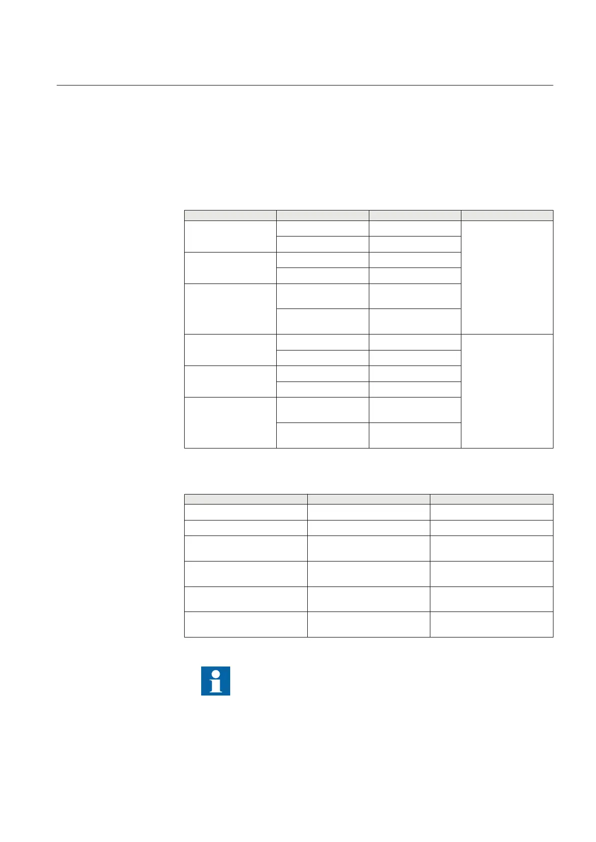
Table 685: 4-wire EIA-485 jumper connectors for COM2
Group Jumper connection Description Notes
X3
1-2 A+ Bias enabled
COM2
4-wire TX channel
2-3 A+ Bias Disabled
X5
1-2 B- Bias enabled
2-3 B- Bias Disabled
X6
1-2
Bus termination
enabled
2-3
Bus termination
disabled
X7
1-2 B- Bias enabled
COM2
4-wire RX channel
2-3 B- Bias Disabled
X8
1-2 A+ Bias enabled
2-3 A+ Bias Disabled
X9
1-2
Bus termination
enabled
2-3
Bus termination
disabled
Table 686: Jumper connectors for COM1 serial connection type
Group
Jumper connection Description
X16 1-2 EIA-485 selected for COM1
2-3 FO_UART selected for COM1
X15 1-2 Star topology selected for
FO_UART
2-3 Loop topology selected for
FO_UART
X24 1-2 FO_UART channel idle state:
Light on
2-3 FO_UART channel idle state:
Light off
It is recommended to enable biasing only at one end of the bus.
1YHT530004D05 D Section 13
IED physical connections
615 series 865
Technical Manual