6243/44 DC Voltage Current Source/Monitor Operation Manual
2.3.2 Battery Charge Test and Discharge Test
2-38
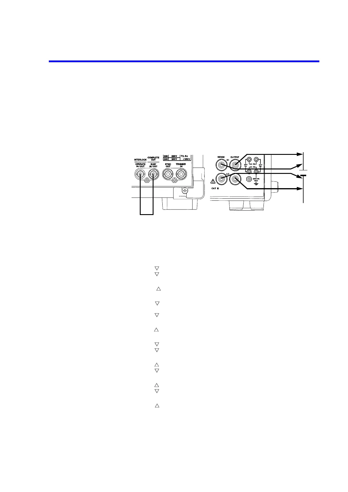
Connecting the DUT
8. Connect the leads using 4-wire as shown in Figure 2-12 to eliminate voltage drop
caused by the leads.
9. Connect the COMPLETE OUT terminal and the OPERATE IN terminal on the
rear panel using the BNC-BNC cable A01036.
The charging and discharging are completed automatically.
Figure 2-12 Connections for Battery Charge and Discharge Test
Charge Test
10. Press the MENU key. Select TIME in the parameter group by rotating the Data
knob.
Press the key and select the Period parameter by rotating the Data knob.
Press the key and press the 1, 0, 0, 0, and ENTER keys.
Period is set to 1000.0 ms.
Press the key twice or press the MENU key, and select SOURCE in the
parameter group by rotating the Data knob.
Press the key and select the Remote Sensing parameter by rotating the Data
knob.
Press the key and select 4 Wire by rotating the Data knob.
Remote Sensing is set to 4 Wire.
Press the key twice or press the MENU key, and select COMPARATOR in the
parameter group by rotating the Data knob.
Press the key and select the Compare parameter by rotating the Data knob.
Press the key and select ON by rotating the Data knob.
Compare is set to ON.
Press the key and select the Upper Data parameter by rotating the Data knob.
Press the key and press the 2, 0, 0, 0, mA, and ENTER keys.
Upper Data is set to +2000.00 mA.
Press the key and select the Lower Data parameter by rotating the Data knob.
Press the key and press the 1, 0, 0, mA, and ENTER keys.
Lower Data is set to +100.000 mA.
Press the key twice or press the MENU key, and select EXT.SIGNAL in the
parameter group by rotating the Data knob.