FOCUS 200 PLUS Installation and Setup Guide
2-2
6.
Determine any conditions within the premises that will require special attention; i.e., safety,
adverse environmental conditions, repairs to deteriorated points, etc.
7.
Advise the data group of the following:
•
Any changes in conditions affecting the customization database.
•
Any corrections in the premises telephone number, address, or customer name.
Power Requirements
The FOCUS 200 PLUS System uses the control unit power supply as the primary power source.
Because the system power is distributed over the RS-485 buses, it is important to keep the voltage
drops along the buses to a minimum (see the
Gateways
section to calculate voltage drops, to ensure that
they do not go below an acceptable level).
Good installation practices will go a long way toward minimizing both the effect of the voltage drops
and the need for adding an external power unit. To this end consideration should be given to:
•
Positioning the gateway(s) with the heaviest load as close as possible to the control unit.
•
Using a run from both RS-485 buses on the control unit so as to divide the total system load
current among the two bus runs.
Where additional power is needed, a 472372 Power Supply Module (in a 472381 Power Unit Housing)
can be introduced at sections of the bus via a gateway. The power supply will provide power for its
associated gateway and for additional sections of the RS-485 bus, as well. For more information
regarding power requirements, see the
Power Requirements
and the
Specifications
sections.
Mounting the Cabinet
Mount the control cabinet to a sturdy wall using fasteners or anchors (not supplied) in a clean, dry area
that is not readily accessible to the general public. The back of the control cabinet has 4 holes for this
purpose. The location must be convenient for the routing of all wiring, and for future repair and
maintenance.
The control unit must be located in a protected area that is armed, unless occupied. If not occupied at any
time, the area must be under 24-hr. protection. This precaution does not apply to any control unit that is
protected against attack.
Be careful when removing knockouts to avoid damaging the control board. Remove the control board from
the control unit, if necessary. Do not drill mounting holes through the backshell. Place the backshell on the
wall, mark the locations of the holes, remove the backshell, and drill the holes.
Installing the Cabinet Lock
Use an ADEMCO No. N6277 Cam Lock and No. P3422-2 Clip for universal commercial cabinets.
1.
Before mounting the circuit board,
remove the metal knockouts for
the wiring entry that you will be
using. DO NOT ATTEMPT TO
REMOVE THE KNOCKOUTS
AFTER THE CIRCUIT BOARD
HAS BEEN INSTALLED.
2.
Fasten the control unit to the
mounting surface, providing
shims or a backboard to prevent
distortion of the backshell.
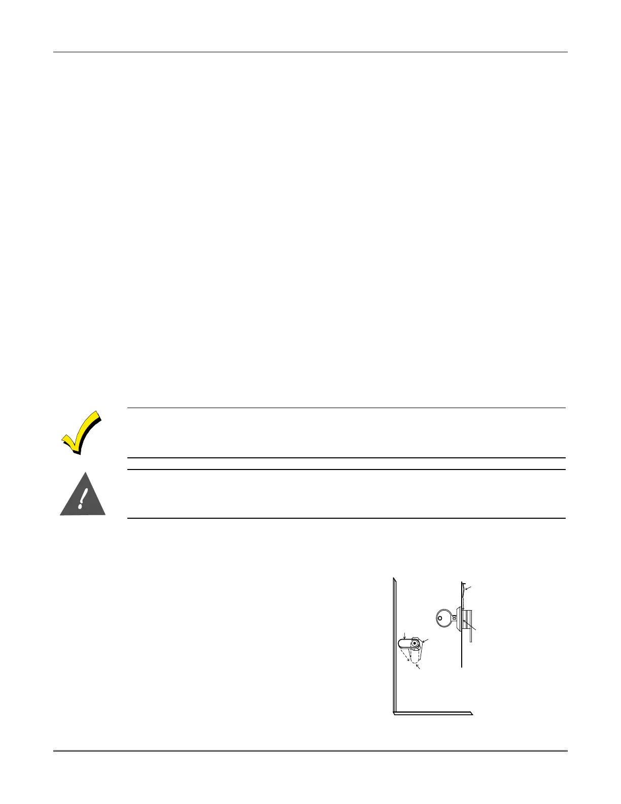
CABINET DOOR BOTTOM
RETAINER
CLIP
RETAINER CLIP
(NOTE POSITION)
RETAINER
SLOTS
LOCKED
UNLOCKED
Figure 2-1: Installing Cabinet Lock
 Loading...


