FOCUS 200 PLUS Installation and Setup Guide
4-4
+
-
-
+
-
+
•
EOL POWER
SUPERVISION
RELAY
MODULE
ADT PART #435243
•
•
4-WIRE SMOKE
OR COMBUSTION
DETECTORS
2000
OHM
EOLR
HEAT
DETECTOR
+
–
REDBLK
VIOLET
+
-
POINT
TERMINALS
(25-38)
12
11
10
9
N.C.
POLE
N.O.
GROUND
CONTROL
PANEL
•
SHOWN POWERED.
RELAY OPENS WHEN
POWER IS LOST.
AUXILIARY
RELAY
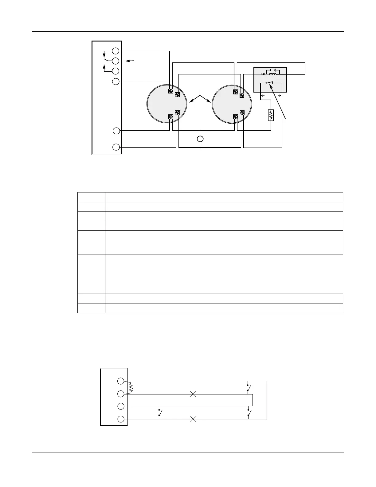
Figure 4-2: 4-Wire Smoke Detector Connections Points 1-8
To wire 4-wire smoke detectors to points 1 - 8 (terminals 25-38), perform the following steps:
Step Action
1 Select compatible 4-wire smoke detectors. Some are listed on the previous page.
2 Connect 4-wire smoke detectors across points 1 through 8 (25 through 38). See
Figure 4-2.
3 If EOL resistors are presently connected across the terminals, remove them.
4 Connect the EOL power supervision relay module (435243) and the 2k EOL resistor at the
last detector on each point. See
Figure 4-2.
Note:
Each point must have its own power supervision relay module.
5
Connect the power wires from the 4-wire smoke detectors and the EOL power supervision
relay module to the control unit. Connect the ground wire to terminal 12, and the positive
power to the normally closed side of the auxiliary relay (terminal 9). See
Figure 4-2.
Note:
Auxiliary power is not automatically reset after an alarm, and therefore must be
momentarily interrupted using the built-in auxiliary relay.
6 Move jumper P3 to short pins 1 and 2, making the auxiliary relay wet (12-volt output).
7 Program the Auxiliary Relay Output to 4-wire smoke detector reset.
Points 3 and 4 Style "D" (Class A Fire Loop) Configuration
The style "D" configuration is a Class A Fire Loop. It can annunciate an alarm condition even with an
open in the wire run. A break or open in the wire run will annunciate a trouble condition on point 3,
but the system can still annunciate an alarm condition, if a sensor is shorted.
Wiring for Style "D" Configuration
2k
EOLR
POINT 4
32
31
30
29
POINT 3
+
-
-
+
CONTROL
PANEL
A B
C
Break #2
Break #1
Figure 4-3: Style "D" Configuration on Points 3 and 4
 Loading...


