FOCUS 200 PLUS Installation and Setup Guide
6-6
Installing an Alarm Housing
U
L
The 471956(7187-101) Alarm Housing and ADEMCO AB12 Bell are UL-approved exterior sounding
devices for local mercantile premises bell certification. For exterior auxiliary BA or FA bell applications,
other sounding devices such as the 471859 (7187-037) Bell Unit may be used, provided applicable UL
installation guidelines are followed.
If 471956 Alarm Housing is being used, install it as follows:
Step Action
1 Mount the alarm housing on an outside wall of the building, visible from a public street. It
should be mounted at least 10 feet above street level, but no higher than the ceiling level
of the fourth story above street level.
2 Install the wiring between the control unit and the alarm housing in conduit, without
boxes or openings unless covers are tampered or welded to the box.
3
Using locally available caulking compound, caulk around the conduit connection at the
rear of the alarm housing to prevent water seepage into the housing.
4
If the alarm housing is flush-mounted, the building wall must include an opening 15"
(38.lcm) H x 24" (61cm) W x 5-1/2”
(14cm) D with a louvered grille (provided by the
customer). Mount the housing within this opening, and affix a sign (supplied by the
customer) that prominently displays the words "BURGLAR ALARM."
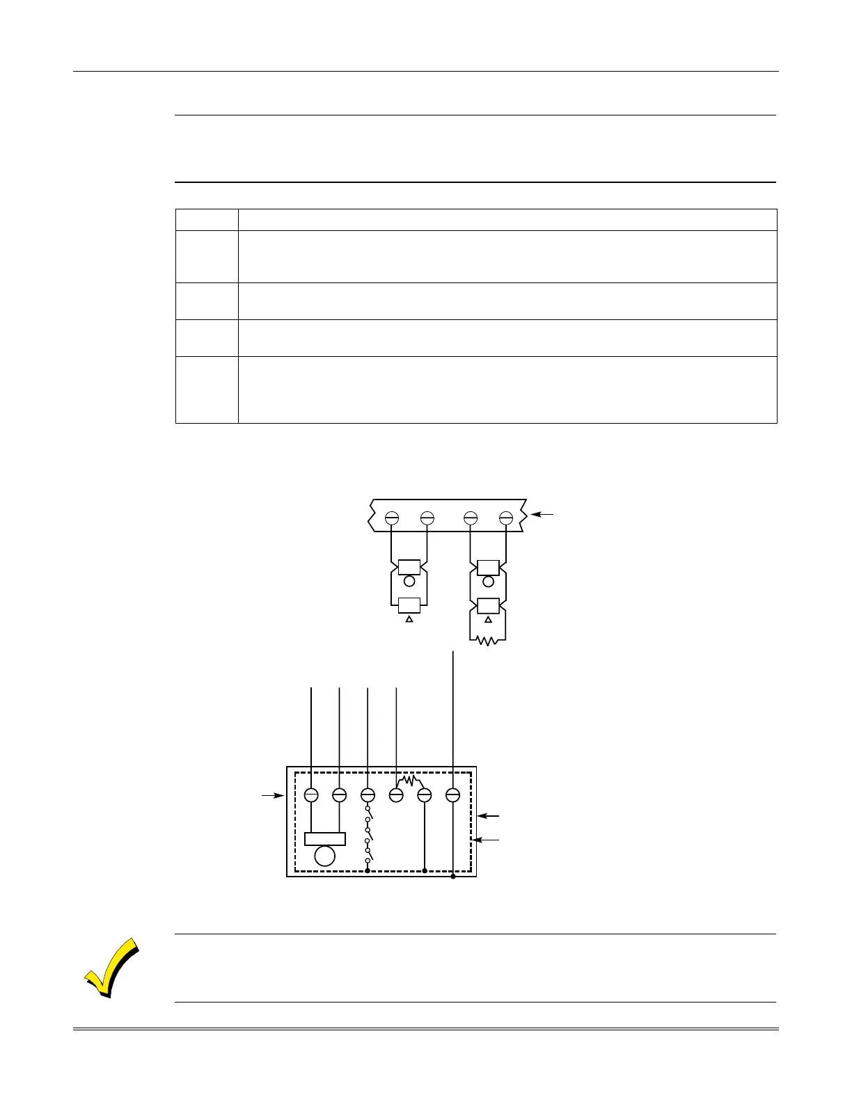
Wiring Bell Outputs
Wire sounding devices to the bell outputs as shown in
Figure 6-1
.
+
–
BELL 1
+
–
BELL 2
2k EOLR
56 7 8
AB12 WIRING NOTES:
• Disconnect the AB12's factory-wired
connection from its terminal #4 to its
outer box.
• Assign point 8 to a BA Group. Program
it as a Supervisory (SPV) Point Type.
• All wiring from AB12 to panel must be
run in conduit.
AB12 BELL/BOX WIRING
TO PANEL'S BELL +
(EG: BELL 1+; TB5)
TO PANEL'S EARTH GROUND
(Terminal 3 or 4)
TO PANEL'S BELL –
(EG: BELL1–; TB6)
TO POINT 8 + (TB38)
TO POINT 8 – (TB37)
BELL
TAMPER
SWITCHES
1
23456
2k EOLR
AB12 OUTER BOX
INNER LINER
WIRING FOR
ADEMCO AB12
COMMERCIAL
BURGLARY
GRADE A BELL
BELL 1 SHOWN AS A
BURGLARY BELL
OUTPUT WITH NON-
POLARIZED
INDICATING DEVICES.
BELL 2 SHOWN AS A
FIRE BELL OUTPUT
WITH POLARIZED
INDICATING DEVICES.
Figure
6-1: External Sounder Connections to the Bell Outputs
If using the bell box tamper, program the option via the downline loader. Otherwise the system will not
detect a "short" on point 8.
 Loading...


