FOCUS 200 PLUS Installation and Setup Guide
5-18
Step Action
5 Snap the Trunk Junction box SCN 148320 around the connections to enhance
appearance.
6
Connect the branch cable to the SIM or SIM Sensor. SIM sensors that have screw
terminals include the smoke detector, the FA Pullbox, motion sensors, and the
horn/strobe. Connect these directly to the branch cable.
7
Splice the SIM module to the branch cable. Use SCN 810953 connectors to splice to the
branch cable.
8 Collect the point description, gateway number, and Hard ID's of all installed SIMs so
they can be programmed into the control unit. Use the Gateway Trunk Log Form to
record the Gateway, Hard ID, BA Group, and point description. Once the data has been
collected, it must be entered into the control unit via the operating panel. See the
Programming
section for the procedure. Once the data has been programmed, any walk-
tests LEDs will function.
The Hard ID label: The top line is the barcode. The second line is in readable text. The
first eight digits are the Hard ID. The next six digits are the Stock Code Number (SCN
#). The next four digits are the manufacturing date codes ("year week"). The last two
digits are for the vendor codes like "P" for Pine Brook.
9 Mark the SIM Sensor point number stick-on labels SCN 146844. Peel off the number
that represents the point number and stick it on the outside of the sensor so it is clearly
visible and can be referred to later.
Sensors cannot be walk-tested unless the sensor's point type, group, gateway, and Hard ID are in the
control unit's database.
IN 0
IN 2
C5
2.3 uf
25V
OUT 0
YEL
COM ( )
BLU
COM ( )
+
BLK
GND
RED
+12V
GATEWAY
TRUNK
CONNECTIONS
TRANSISTOR
SWITCH
RED-WHT
BLK-WHT
ORG
AL-TBL
BLU-WHT
TMPR
WHT
+12V
472366 SIM
+12V
GND
+12V
GND
OUTPUT POWER
(FOR INPUT POINT, TRANSISTOR SWITCH IS
CONTINUOUSLY CLOSED TO SUPPLY SENSOR POWER.
FOR OUTPUT POINT, TRANSISTOR SWITCH CLOSES ONLY
WHEN COMMANDED FROM CONTROL UNIT.)
SYSTEM-POWERED
SENSOR
W/ TRANSFER CONTACTS
AND TAMPER
NON-POWERED
SENSOR
W/ BREAK-ONLY CONTACT
(NO TAMPER)
IN 0
IN 2
MICROPROCESSOR
INPUT
OUT 0
MICROPROCESSOR
OUTPUT
CONDITION IN 0 IN 2
NORMAL 6V GND
ALARM GND GND
TAMPER 6V 12V
OPEN LOOP 12V 12V
CONDITION IN 0 IN 2
NORMAL 6V GND
ALARM 12V GND
TAMPER 6V 12V
OPEN LOOP 12V 12V
T
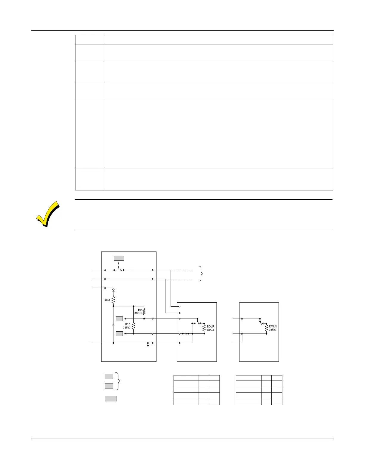
Figure 5-7: SIM Wiring to System-Powered and Nonpowered Sensors
 Loading...


