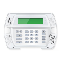
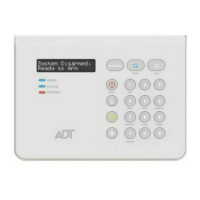
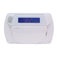
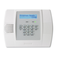
FOCUS 200 PLUS Installation and Setup Guide
10-6
Step Action
5 Install the battery on the ACIU circuit board and fasten it with tie wraps. Mark the
battery with the date of installation.
6 If you are using a 248116 Tamper Kit, install it on the ACIU circuit board at this time.
7 Install the ACIU circuit hoard in the housing unit.
8 Mark the housing with the number that will be transmitted to the CCC for an ACIU
trouble, tamper, or restore condition. This number is related to the communication unit
number of the ACIU. Also, be sure to record this number on the installation layout
diagram so that the ACIU can be readily located, if necessary.
Wiring the Access Control Interface Unit
To wire the ACIU, perform the following steps:
Step Action
1 At the control unit, make sure the power switch is in the "OFF" position.
2
Run the buses as required and make sure to appropriately tag them. Limit each RS-485
bus to a single wire run.
Note:
It
is important to appropriately tag the cables so they can readily be identified. This
is especially important if troubleshooting becomes necessary at some future date.
3
Cut the trunk cable and remove enough sheathing and insulation from each wire to allow
fastening under the pressure plate of a terminal strip screw.
4 Measure the resistance between the black and red conductors (the (+) lead of the meter to
the red conductor and the (-) lead to the black conductor). A reading less than 12 ohms
indicates a short on the power conductors or an excess of protection points. Make the
necessary corrections before proceeding.
5 Connect the RS-485 cable to TB1 of the ACIU
.
Identify terminal wires so that the proper
wires can be connected to each terminal (see
Figure 10-1
)
.
6 Connect the battery leads to the connector on the circuit board.
7 Connect the RS-485 bus cable to the control unit (see table below).
Wire Gauge/Color Function
RS-485 #1
Terminal
RS-485 #2
Terminal
#19 AWG Blue RS-485 17 21
#19 AWG Yellow RS-485 18 22
#16 AWG Red + 12 VDC Power 19 23
#16 AWG Black DC Return Power 20 24
8 Power up the control unit to allow the ACIU battery to charge.
Using Readers, Keyloks, and Operating Panels
The cards and keys that are employed for ADT applications are listed in the Summary of Access
Card/Key Readers Table, shown later in this section. They all come pre-coded and ready to use as soon
as the code has been enrolled into the database of the control unit. The control unit stores the entire
code number, (site code plus individual person's code), so there is no need for the use of special site
codes for the cards or keys. Existing customer cards for a given type of reader may be utilized for
FOCUS 200 PLUS system.
The FOCUS operating panel can control access not only through card/keyreaders, but also through
keypad entry of a valid 6-digit code.

 Loading...

