Section 9 – J5 Output Triggers
9-5
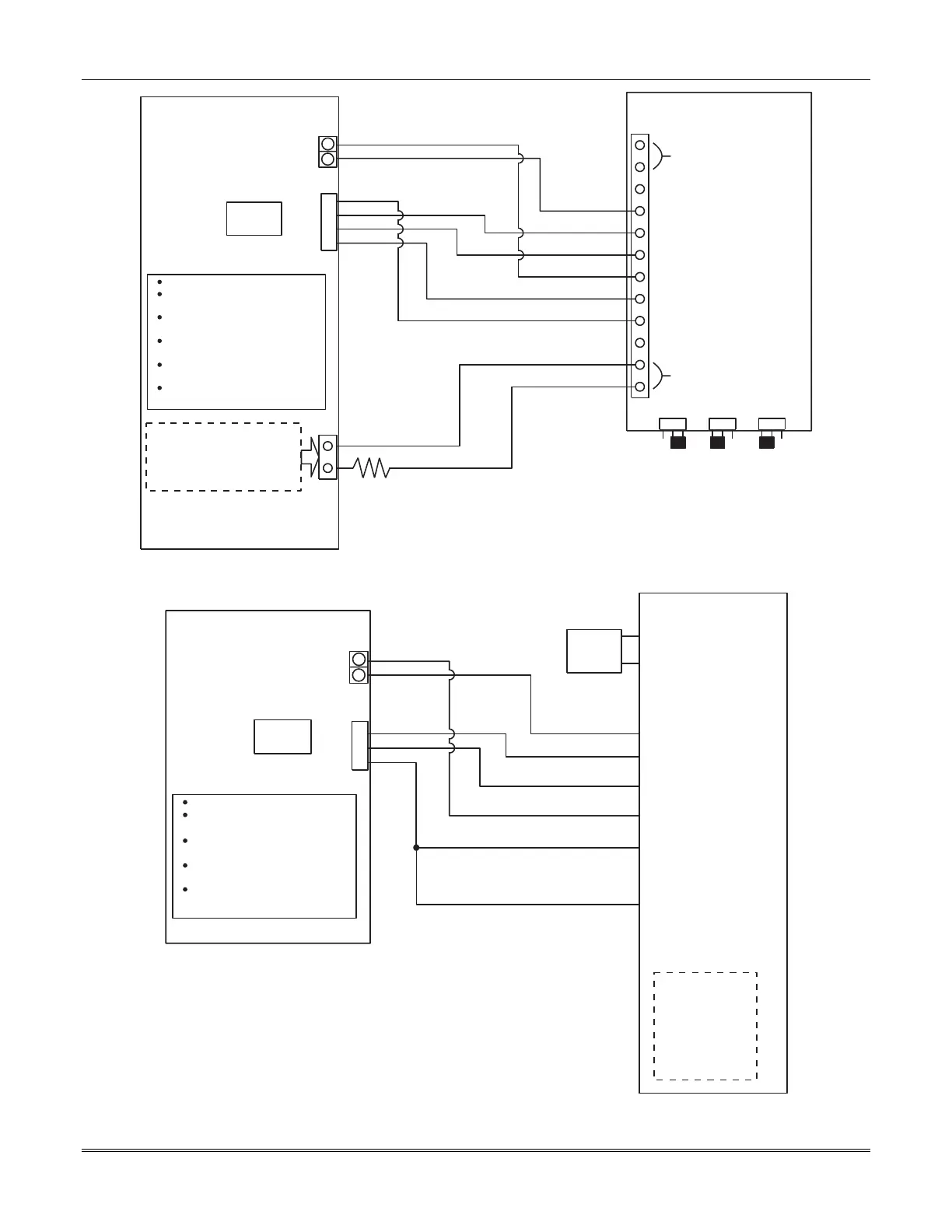
AUX. Relay N.O.
Ground
Output
Triggers
Violet
Yellow
Gray
FOCUS 200 PLUS
FOCUS 200 PLUS Setup:
Set the P3 Jumper to 'WET'
Program the AUX. Relay to activate
on any BA [ABA]
Program Output 5 (Point 252) to
activate on BA Off (type 20, OFC)
Program Output 6 (Point 253) to
activate on Fire (type 21, FA)
Program Output 7 (Point 254) to
activate on Holdup (type 23, HU)
Program Output 8 (Point 255) to
activate on Telco Fault (type 16)
Trigger
Ground
2k EOLR
Zone1
Zone 2
Zone 3
Zone 4
ECP In
ECP Out
Radio Fault
Output
Power
16.5VAC / 40VA
J3 J2 J1
A
B
GND
+V
GND
+V
7830R
SafetyNet Radio
White
Use any of the eight Hardwired
Inputs (ZN 1-8) on the control and
Program this point as an FI
(Type 1), or an SPV (Type 13) to
monitor Radio Fault
11
12
J5
6
7
8
9
Out 5
Out 6
Out 7
Out 8
Figure 9-2: Configuration of the 7830R to the J5 Output Triggers
16.5
40VA
AC1
AC2
+ Trigger Voltage
- Trigger (GND)
Zone 1 (FA)
Zone 2 (HU)
Zone 3 (BA)
Zone 4 (Telco Fault)
Zone 5
Zone 6 (Enable Radio)
Radio Fault Relay 1
Radio Fault Relay 2
ADEMCO 7835C
New Programming
Options:
Q 27= Y
Q27a=Y
Q27b=Y
Q27c=Y
Q27d=N
Q27e=N
AUX. Relay N.O.
Ground
Output
Triggers
FOCUS 200 PLUS
FOCUS 200 PLUS Setup:
Set the P3 Jumper to 'WET'
Program the AUX. Relay to activate
on any BA [ABA]
Program Output 6 (Point 253) to
activate on Fire (type 21, FA)
Program Output 7 (Point 254) to
activate on Holdup (type 23, HU)
Program Output 8 (Point 255) to
activate on Telco Fault (type 16)
11
12
J5
7
8
9
Out 6
Out 7
Out 8
Figure 9-3: Configuration of the 7835C to the J5 Output Triggers
 Loading...


