Section 3 – Installing the Operating Panels
3-3
To mount and wire the operating panel, perform the following steps:
Step Action
1
Locate the operating panel(s) where the user may conveniently turn BA protection to Day
Set or Nite Set. The right-hand side of the operating panel should be located no closer than
4” from a side wall.
2 Run the buses as required and make sure to appropriately tag them, so that can be readily
identified at some future time, if maintenance becomes necessary. Limit each RS-485 bus
port to a single wire run.
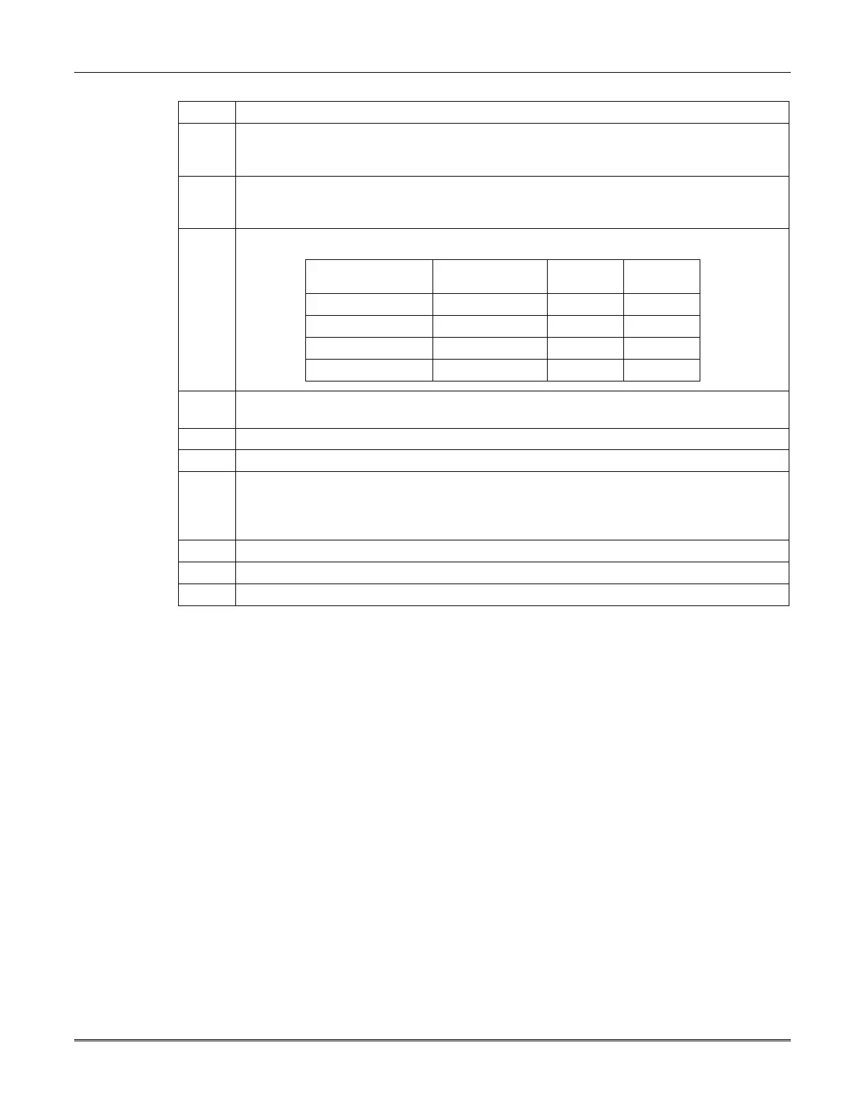
3 Connect the RS-485 bus cable to the control unit (see table below).
Wire Gauge/Color Function RS-485 #1
Terminal
RS-485 #2
Terminal
#19 AWG Blue RS-485 17 21
#19 AWG Yellow RS-485 18 22
#16 AWG Red + 12 VDC Power 19 23
#16 AWG Black DC Return Power 20 24
4 Remove the nylon screw on the bottom of the operating panel and separate the back plate
from the front of the unit.
5 Mount the back plate to the wall using any of the appropriate holes.
6 Connect the operating panel wires to the RS-485 cable, matching color to color.
7 Each device that connects to the RS-485 bus has a terminating jumper designated E1 (see
Figure 3-1
). Inserting the jumper connects a terminating resistor; removing the jumper
disconnects the resistor. Insert the jumper on the last device on each RS-485 bus. All other
devices on the RS-485 bus run must have the jumper removed.
8 Reconnect the front plate to the back plate and reinsert the nylon screw.
9 Install the instruction label at the rear of the operating panel in the slot provided.
10 Repeat the steps for each operating panel.
Addressing the Operating Panels
The control unit must be powered up to address the operating panels. This can be done now, by
temporarily applying the AC power, or can be done later, after the AC and standby battery wiring is
complete. See the
Power Requirements
section.
Communication Group Number and Unit Number
Each operating panel must be addressed with a communication group number and a unit number for
proper communication with the control unit. The group number and unit number serve to supervise the
panel, permitting the control unit to periodically address each panel and verify a response.
There are two group numbers (numbers 00 and 01) that are reserved for the operating panels (the
communication group default value is number 31). The unit numbers available are 0 through 7. We
recommend that the unit numbers start with the default value 0 for the first operating panel in the
communication group, and continue with 1 for the second panel, and so on, up to unit number 7.
 Loading...


