Section 5 - Gateways
5-19
NOTES:
1. POINT OPTION 3="Y".
2. DIAGNOSTIC OPTION ENABLED.
3. IF LED DISABLE OPTION = "N", LED WILL LIGHT WHEN DETECTOR
ALARMS PROVIDED POINT IS NOT BYPASSED.
IF LED DISABLE OPTION = "Y", LED WILL LIGHT WHEN DETECTOR
ALARMS ONLY IN WALK TEST OR SERVICE MODE PROVIDED POINT
IS NOT BYPASSED.
BLU
COM+
YEL
COM-
+12V
POWER
DATA
IN/OUT
OUT 0
OUT 1
IN 0
IN 1
IN 2
SIM
INTERFACE
GND
LED
SEE
NOTE 3
SEE NOTE 1
SEE NOTE 2
DIAGNOSTIC
OUTPUT
ALARM OUTPUT
SELF TEST
INPUT
SENSOR
POWER +12V
SENSOR
ELEMENT
GND
TAMPER
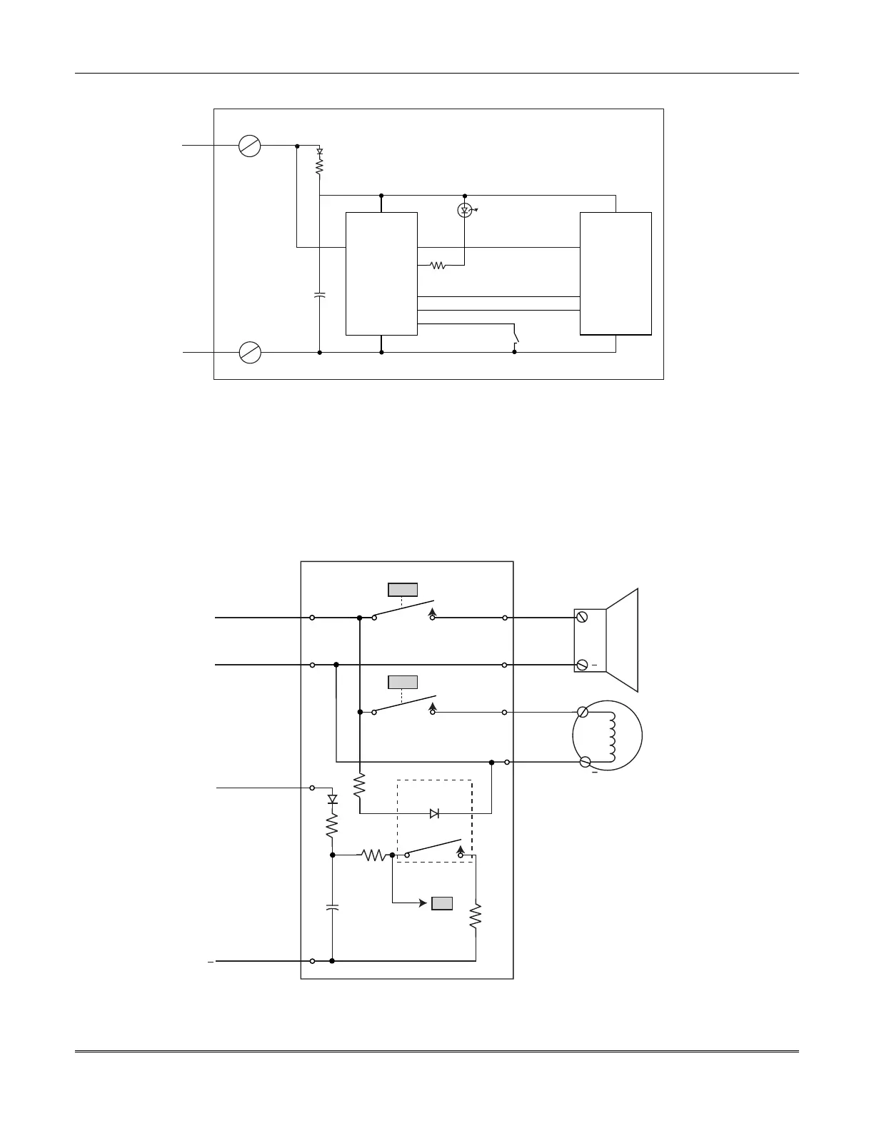
Figure 5-8: Connection for a Gateway Loop Powered SIM Sensor
RED
BLACK
+12V
GND
BLU
YEL
COM+
COM-
33K
TRANSISTOR
SWITCH
33K
POWER
SUPERVISION
TRANSISTOR
SWITCH
TRANSISTOR
SWITCH
OR
BLK/W
RED/W
BLK/W
IN 0
OUT 0
OUT 1
472488 HORN-STROBE SIM
+
+
STROBE
HORN
Figure 5-9: SIM Wiring to a Horn and Strobe
 Loading...


