FOCUS 200 PLUS Installation and Setup Guide
9-6
AUX. Relay N.O.
Ground
Output
Triggers
FOCUS 200 PLUS
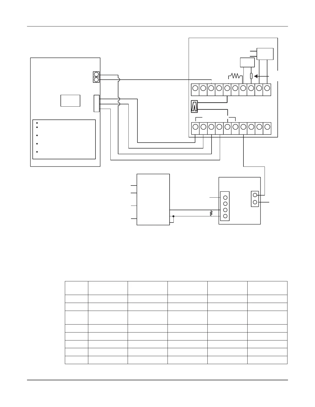
FOCUS 200 PLUS Setup:
Set the P3 Jumper to 'WET'
Program the AUX. Relay to activate
on any BA [ABA]
Program Output 6 (Point 253) to
activate on Fire (type 21, FA)
Program Output 7 (Point 254) to
activate on Holdup (type 23, HU)
Program Output 8 (Point 255) to
activate on Telco Fault (type 16)
11
12
7
8
9
J5
Out 6
Out 7
Out 8
7920SE
TB1
TB2
Tamper
No. 112
ALTRONIX
RBTUL
Org
Blue-Wht
White
Fix Instant BA pt
To SIM Gateway Trunk
Red-Wht
Gnd Blk
+12V Red
Com (-) Yel
Com (+) Blue
To CP + 12V
Pos
NO
C
NC
Tr ig
Neg
To CP GND
472366 SIM
Radio
1
2
3
4
5
6
7
8
9
10
OK
Z6Z3 Z4 Z5Z1 Z2
Earth
1
2
3
4
5
6
7
8
9
10
Blk
TEST GND
Red
GND
10k EOLR
XMFR
Imputs
33k EOLR
879-126
Battery
No. 1349
16.5VAC
40VA
Zone
Fuse
No. 90-12
3A, 32V
CKT
Zone Inputs 1-6
Yellow
Gray
Violet
Figure 9-4: Configuration of the 7920SE to the J5 Output Triggers
Programming the Output Triggers
The output triggers are points 248 through 255 (output triggers 1 through 8). For information about the
procedure, refer to the
Programming
section.
Defaults for the Output Triggers:
Point Description
472412 Wire
Color
Default Type Gateway # Hard ID
248 Trigger 1 Blue PLC 8 111
249 Trigger 2 Brown PLC 8 112
250 Trigger 3
(Tamper)
Green PLC 8 113
251 Trigger 4 Red PLC 8 114
252 Trigger 5 White PLC 8 115
253 Trigger 6 Yellow PLC 8 116
254 Trigger 7 Gray PLC 8 117
255 Trigger 8 Violet PLC 8 118
 Loading...


