FOCUS 200 PLUS Installation and Setup Guide
8-2
Wiring the AC Module
The module draws 250mA from the FOCUS 200 PLUS’ auxiliary power #2 output. Be sure to include this
current draw in the power calculations.
To wire the AC Communicator, perform the following steps:
Step Action
1
Power down the control unit before making any connections to the AC Module.
2
Connect the telephone lines to the module. See
Figure 8-1
.
Notes:
1. If you are using AC telephone lines, connect these to terminals 1 & 2 (see
Figure 8-2)
.
2. If you are using DVACS telephone lines or RS232 port, connect these to
terminals 4 - 8.
Maximum length of RS232 cable is 50 feet
(see
Figure 8-3)
.
3. If you are using DC telephone lines, connect these to terminals 9 - 12 (see
Figure 8-4)
.
3 Connect the ribbon cable (supplied) from the 9-pin header on the module to J6 on the
control unit’s PC board. Be sure the ribbon cable does not run under the AC module
board.
The J6 header is static sensitive. Make connections to the header with the
power to the control unit off and after grounding yourself.
4
Connect the module’s earth ground (terminal 3) to the control unit’s earth ground
(terminal 3 or 4), using 16AWG wire.
5 If you are using multiple AC Communicator modules, set the JL/JK header. See the text
that follows for the correct configuration.
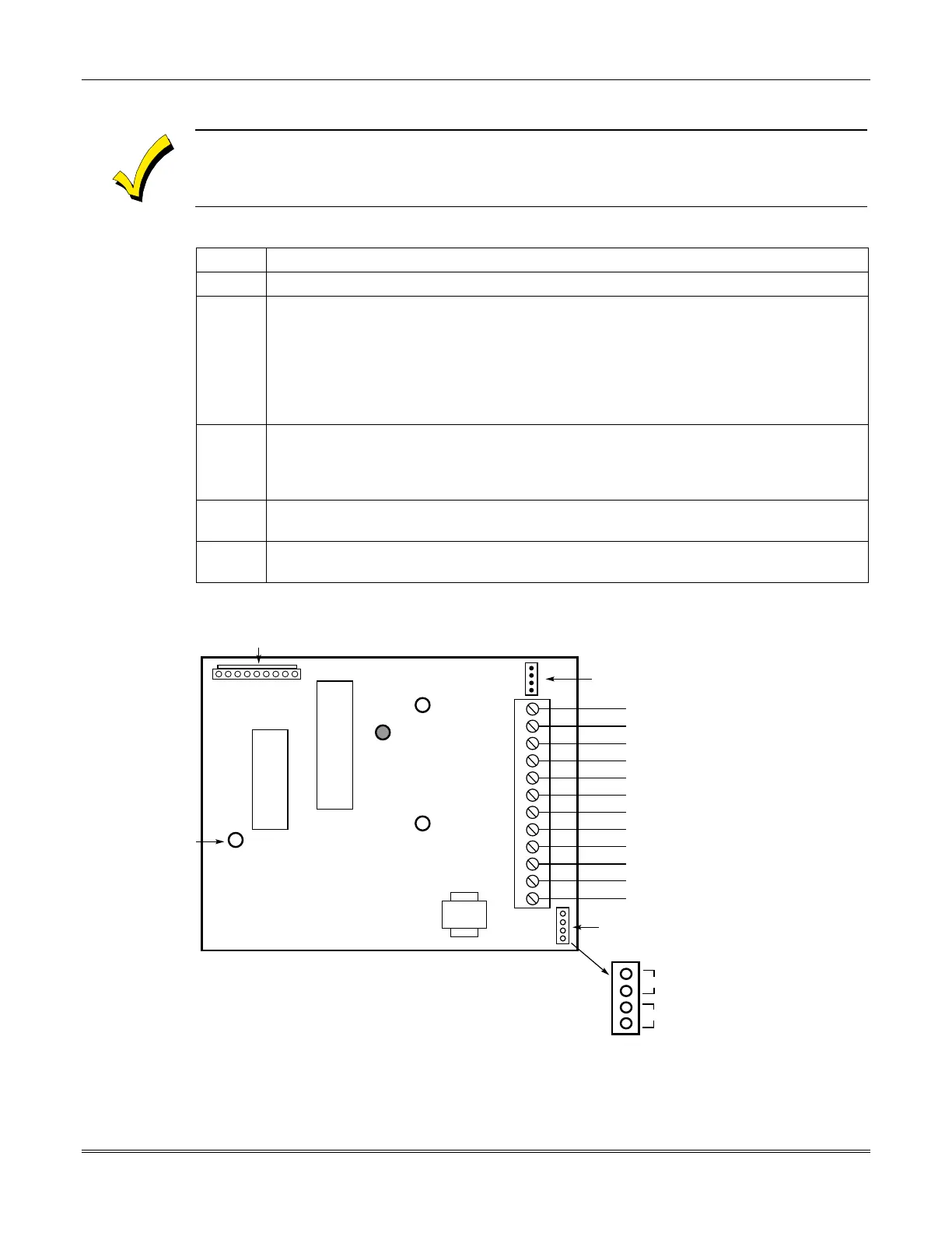
12
11
10
9
8
7
6
5
4
3
2
1
COM 2+
COM 2–
COM 1+
COM 1–
GROUND
TXD
RXD
RTS
CTS
EARTH GROUND (NOTE 4)
RING
TIP
}
}
}
TO PAIR OF DC
TELEPHONE LINES
TO DVACS TELEPHONE LINE
(OR RS232 PORT)
TO AC TELEPHONE LINE
4-PIN JL/JK HEADER
JK
JL
AC TELEPHONE LINE IMPEDANCE
MATCHING JUMPERS.
SEE TEXT FOR SETTINGS.
472491 ADT AC COMMUNICATOR MODULE
123456789
9-PIN HEADER
CONNECTION TO J6.
SEE NOTE 2.
MOUNT MODULE
TO MAIN PCB
USING 3
STANDOFFS
(SUPPLIED).
STANDOFFS
SNAP INTO 3
HOLES SHOWN.
NOTE 1: MODULE DRAWS 250mA @ 12VDC.
NOTE 2: CONNECT RIBBON CABLE (SUPPLIED) TO J6 ON THE CONTROL
UNIT’S CIRCUIT BOARD.
NOTE 3: THE MODULE TURNS THE ACTIVITY LED ON WHEN IT DETECTS AN
INCOMING CENTRAL STATION POLL. IF THE INCOMING POLL IS NOT
ADDRESSED TO IT, THE MODULE TURNS THE ACTIVITY LED OFF
IMMEDIATELY. IF THE INCOMING POLL IS ADDRESSED TO IT, THE
MODULE KEEPS THE ACTIVITY LED ON UNTIL THE NEXT POLL
WHICH IS NOT ADDRESSED TO IT.
NOTE 4: CONNECT THE MODULE’S EARTH GROUND TO THE PANEL’S EARTH
GROUND (TERMINALS 3 OR 4) USING 16 AWG WIRE.
ACTIVITY LED
(GREEN)
(NOTE 3)
NOT USED
}
Figure 8-1: AC Communicator Module Wiring
 Loading...


