FOCUS 200 PLUS Installation and Setup Guide
8-4
12
11
10
9
8
7
6
5
4
3
2
1
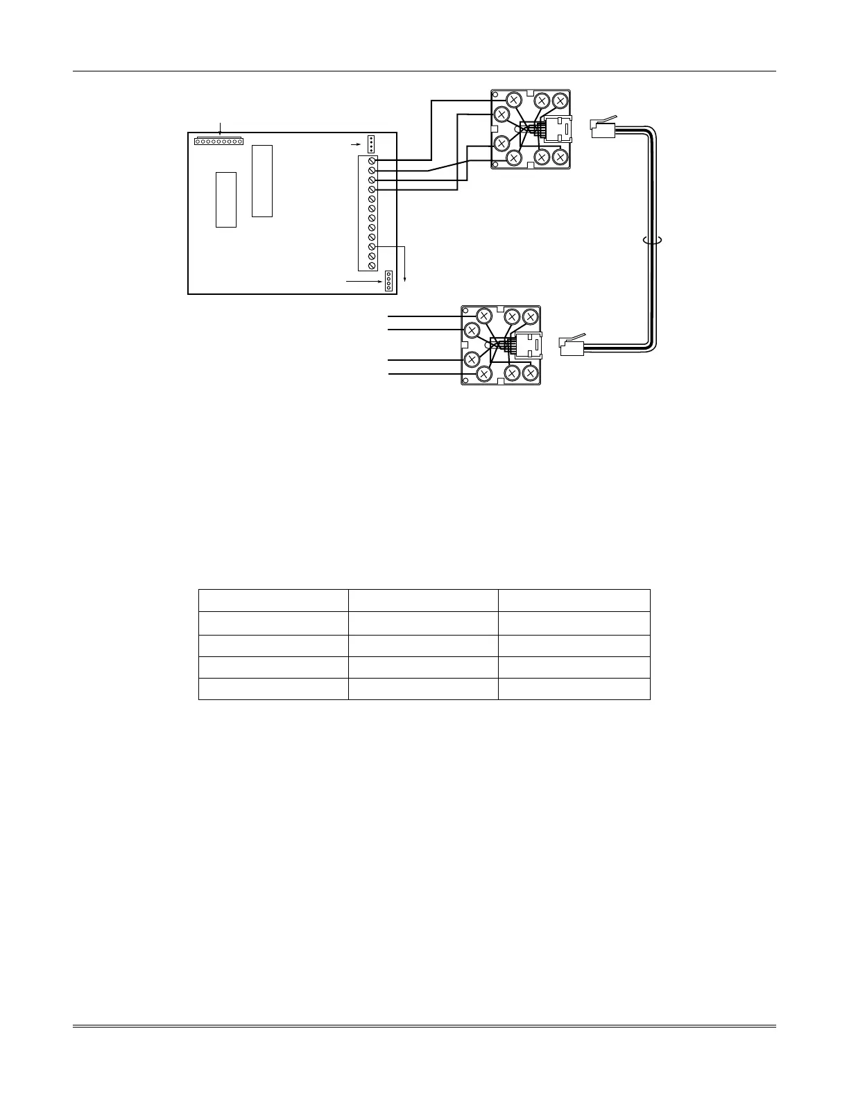
(SEE NOTE 1)
4-PIN JL/JK
HEADER
CONNECT RIBBON CABLE FROM
9-PIN HEADER TO J6 ON THE
CONTROL UNIT'S CIRCUIT BOARD
NO
CONNECTION
}
EARTH GROUND
YEL
GRN
RED
BLK ORG
GRY
BRN
BLU
YEL
GRN
RED
BLK ORG
GRY
BRN
BLU
TELCO
CORD
COM 2+
RJ31X TELCO JACK
RJ31X TELCO JACK
472491 ADT AC COMMUNICATOR
COM 1-
COM 1+
COM 2-
COM 1-
COM 2+
COM 2-
COM 1+
TO UCS
Note 1: Not used on DC communication
Figure 8-4: AC Communicator Module Wiring Using DC Telephone Lines
Using Multiple AC Communicator Modules
A total of four AC Communicator modules may be connected in parallel with the same dedicated AC
telephone line. Multiple modules are configured by setting the JL/JK plugs each module.
The JL/JK header has jumper plugs (supplied) that must be properly configured when one or more
modules are connected to a dedicated AC telephone line. The table below indicates when to install the
jumper plugs on the JL and JK positions of this header. See
Figure 8-1.
Number of Modules JL Jumper Plug JK Jumper Plug
1 module Installed Installed
2 modules Not Installed Installed
3 modules Installed Not Installed
4 module Not Installed Not Installed
Programming for the AC Communicator Module
Programming for the AC Communicator Module can only be done via downline loading.
 Loading...


