FOCUS 200 PLUS Installation and Setup Guide
5-22
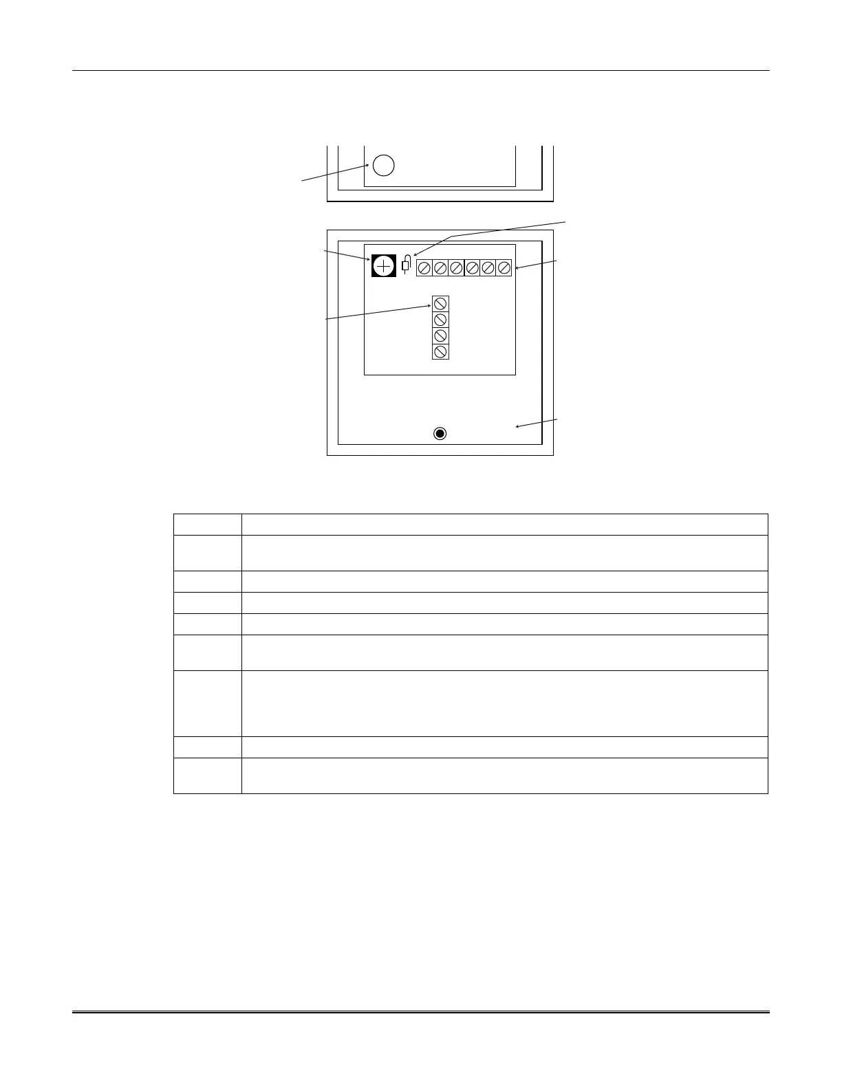
Mounting and Wiring the Loop Interface Module
J1
123456
TB2
1 (BLK)
2 (RED)
3 (YEL)
4 (BLU)
TA
248116 TAMPER SWITCH
(ORDERED SEPARATELY)
(NOTE 1)
TAMPER SWITCH
OPERATOR
SIM GATEWAY
TRUNK CONNECTIONS
LOOP
CONNECTIONS
JUMPER J1
(REMOVE IF
USING TAMPER)
471943
HOUSING UNIT
Figure 5-13: Loop Interface Module
To mount and wire the LIM, perform the following steps:
Step Action
1 Mount the housing unit in a location where the LIM will be protected from tampering or
damage caused by machinery-moving equipment.
2 Record the Hard ID number of the LIM and its associated gateway.
3
Snap the LIM circuit board into the housing.
4 Make the wiring connections from the LIM to the gateway (see
Figure 5-13
).
5 Make the wiring connections from the LIM to the sensor (see
Figures 5-14
and
5-15
). The
loop resistance must not exceed 300 ohms.
5 Using a 148380 Label (sensor number sheet), peel off the appropriate sensor point
number and stick it onto the cover of the housing unit. We recommend that a label
indicating the type of sensor involved and its location be affixed to the inside front cover
of the housing unit.
6 Close the cover of the housing unit.
7
Load the LIM point data into the control unit. See the
Programming
section for
information about the procedure.
 Loading...


