+-
SMOKE
2
-W
IR
E
S
M
O
K
E
D
E
T
E
C
T
O
R
L
O
O
P
N.C.
N.O.
2k (note 2)
+-
N.C.
2k
N.O.
Data
Data
+
-
J5
BELL
HORN
BELL
HORN
+-
SMOKE
N.C.
N.O.
2k
+-
N.C.
N.O.
+-
N.C.
N.O.
+-
N.C.
N.O.
+-
N.C.
N.O.
+-
N.C.
N.O.
2k
2k
2k 2k 2k
2k (note 2)
2k
AC WIRING IS
SUPERVISED
BELL 1
BELL 2
+
+- -
ALARM POLARITY SHOWN
FIRE CKTS: Supervise using 2k EOLR.
Use polarized sounding devices.
BURG CKTS: Supervision not req'd.
EOLRs not req'd. May use non
polarized devices. Ratings: 12VDC, 1.7A max.
See note 1. See instructions to enable/disable
supervision and for compatible devices.
N.C.
WET/DRY
N.O
.
AUX RELAY (FORM C)
programmable response (not supervised)
WHEN WET: 12V terminal 10,
1.7A max., see note 1.
WHEN DRY: No voltage on terminal 10,
Contact Rating: 28V, 2A max.,
resistive loads.
GROUND
2
-W
IR
E
S
M
O
K
E
D
E
T
E
C
T
O
R
L
O
O
P
1
2
3
4
5
6
7
8
9
REFER TO INSTRUCTIONS K3471 FOR ADDITIONAL INFORMATION
WARNING: OWNER'S INSTRUCTION NOTICE NOT TO BE REMOVED
RJ31X
MAIN
PHONE JACK
CONNECTION OF THE FIRE ALARM
SIGNAL TO A FIRE ALARM HEAD-
QUARTERS OR A CENTRAL STATION
SHALL BE PERMITTED ONLY WITH
THE APPROVAL OF THE LOCAL
AUTHORITY HAVING JURISDICTION.
THE BURGLARY ALARM SIGNAL
SHALL NOT BE CONNECTED TO A
POLICE EMERGENCY NUMBER.
Connect
RJ31X using
cable supplied.
Supervision is
programmable.
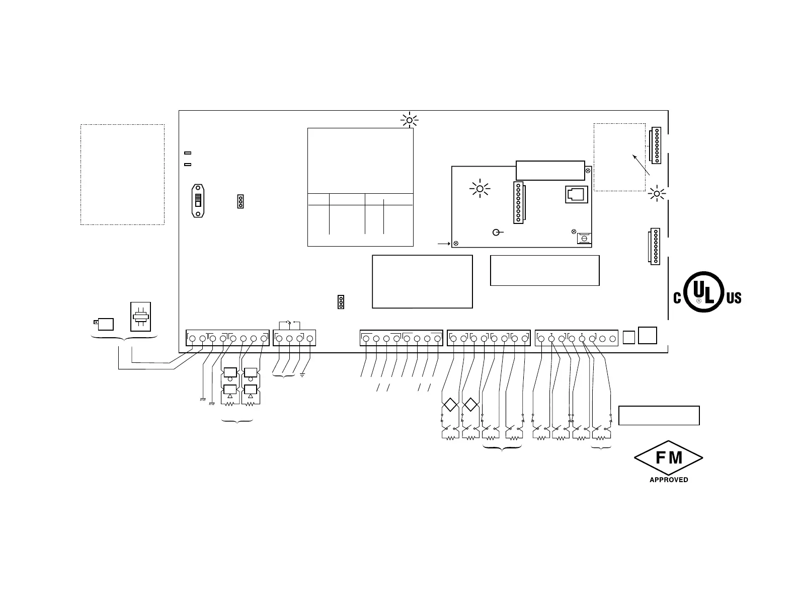
POINT 1-8 NOTES
• All points provide Style B supervision
• Point resistance (excluding EOLR):
- Points 1, 2: 100 ohms max
- Other points: 300 ohms max
• Point response: 350 - 500mS (all points)
• Ratings for points 1, 2:
- 10 - 14VDC
- 2mA max for smoke det. (up to 16 detectors
of the type specified in the instructions
can be used)
• UL compatibility ID: A
Do not mix fire and burg. sensors on one loop.
N.C. contacts for burg. usage only.
BELL OUTPUTS
AUX. RELAY
RS-485 #1
POINT 2POINT 1
POINT 3
TRNSFMR
POINT 5 POINT6
POINT 7
POINT 8
TEST BURGLARY SYSTEM WEEKLY
JUMPER P4
ALARM CURRENT
Pins 1 & 2 shorted = 2.3A
Must use with 47204 transformer.
Pins 2 & 3 shorted = 1.5A
Must use with 443216/N8167
transformer.
472404 wired-in
transformer with
enclosure
INPUT: 120VAC, 1.0A,
60Hz connect to a
dedicated circuit
OUTPUT: 18VAC, 72VA
INPUT
OUTPUT
BL
BL
BKWH
443216 or N8167 plug-in
transformer (optional)
INPUT: 120VAC,
0.59A, 60 Hz connect
to unswitched outlet
OUTPUT: 18VAC, 50VA
NOTE:
443216 may not be used for listed commercial fire
installations. Total alarm current is limited to 1.5A.
Short pins 2 & 3 on P4.
472404 may be used for all listed commercial (burg,
fire, burg/fire) installations. Total alarm current is
limited to 2.3A, see note 1. Short pins 1 & 2 on P4.
WARNING:
THIS UNIT MAY BE PROGRAMMED TO
INCLUDE AN ALARM VERIFICATION
FEATURE THAT WILL RESULT IN A DELAY
OF THE SYSTEM ALARM SIGNAL FROM
THE INDICATED FIRE CIRCUITS. THE
TOTAL DELAY (CONTROL UNIT PLUS
SMOKE DETECTORS) SHALL NOT EXCEED
60 SECONDS. NO OTHER INITIATING
DEVICES SHALL BE CONNECTED TO
THESE CIRCUITS UNLESS APPROVED BY
THE LOCAL AUTHORITY HAVING
JURISDICTION.
CIRCUIT
(POINT)
CONTROL UNIT
DELAY-SEC
SMOKE DETECTOR
MODEL DELAY-SEC
THE DELAY TIME MARKED ON THE INSTALLED
DETECTOR(S) IS TO BE USED
BACK-UP LINE SEIZE
LED (GREEN)
Connect to main PCB
header J6 using ribbon
cable (supplied)
BACK-UP TLM ON HOOK
VOLTAGE THRESHOLD (BLUE)
INTACT: 25V
CUT: 13V
OPTIONAL 472402A BACK-UP DIALER MODULE
BACK-UP
PHONE JACK
SEE TELCO
JACK SHOCK
WARNING
BELOW
BACK-UP DIALER EARTH
GROUND SCREW
(wire to main PCB,
terminal 3 or 4)
Attach 472402A
module to main
PCB using 3
standoffs
(supplied)
RJ31X
(connect using supplied cable)
Supervision is programmable
The 472402A Dialer
Complies with FCC Rules, Part 68
FCC Reg. No.: AC398U-68628-MO-N
Ringer Equivalence: 0.7B
12345678
9 101112 1718192021222324 2526
27
28 29
30
31
32
33 34 35 36
37
38 39 40
RS-485 #2
+
-
Blue Yel Red Blk
SERVICE
JACK
-
BLK
BATTERY TABS
+
RED
J6
1
2
3
4
5
6
7
8
9
POINT 4
GND
FOCUS 200 PLUS SUMMARY OF CONNECTIONS
Points 3 & 4 may
be set for a Style "D"
configuration.
Bell Box
Tamper
POWER SWITCH
1
2
3
P4
P3
ON
OFF
WARNING: TO PREVENT
RISK OF ELECTRICAL SHOCK,
DISCONNECT TELCO JACK
BEFORE SERVICING THIS PANEL.
Blue Yel Red Blk
Data
Data
NOTE 3:
See instructions for max. # of
keypads and wire run length
restrictions.
NOTE 1:
The combined standby current
drawn from aux pwr #2, aux pwr #3
and aux relay terminal 10 (when
wet) can not exceed 1.0A. The
combined alarm current drawn
from aux pwr #2, aux pwr #3, aux
relay terminal 10 (when wet), bell 1
and bell 2 cannot exceed 1.5A
when 443216 or N8167 transformer
is used, and 2.3A when 472404
transformer is used.
NOTE 2:
Use 472411 2k EOLR for listed fire
installations. (supplied)
NOTES
THIS DEVICE COMPLIES WITH PART 15 OF FCC RULES.
OPERATION IS SUBJECT TO THE FOLLOWING TWO
CONDITIONS: (1) THIS DEVICE MAY NOT CAUSE HARMFUL
INTERFERENCE, AND (2) THIS DEVICE MUST ACCEPT ANY
INTERFERENCE RECEIVED, INCLUDING INTERFERENCE
THAT MAY CAUSE UNDESIRED OPERATION.
THIS EQUIPMENT SHOULD BE INSTALLED IN
ACCORDANCE WITH THE NATIONAL FIRE
PROTECTION ASSOCIATION'S STANDARD 72,
CHAPTER 3 (NATIONAL FIRE PROTECTION
ASSOC., BATTERYMARCH PARK, QUINCY,
MA. 02269). PRINTED INFORMATION DESCRIBING
PROPER INSTALLATION, OPERATION, TESTING,
MAINTENANCE, AND REPAIR SERVICE IS TO BE
PROVIDED WITH THIS EQUIPMENT.
Make connections
using 472412 cable
(not supplied)
Backup Dial Header472402A
or AC communication module
472491 Jack
JUMPER P3 Aux Relay Setting
Pins 1 & 2 shorted = wet
Pins 2 & 3 shorted = dry
1. GROUND (BLACK)
2. OUT 1 (BLUE)
3. OUT 2 (BROWN)
4. OUT 3 (GREEN)
5. OUT 4 (RED)
6. OUT 5 (WHITE)
7. OUT 6 (YELLOW)
8. OUT 7 (GRAY)
9. OUT 8 (VIOLET)
Ratings:
Low Output: 0.7V thru 100 ohm
can sink 33mA with 4V drop
High Output: 12V thru 4k ohm
J5 VOLTAGE TRIGGERS
(not supervised)
See instructions for trigger use
and programming.
E
A
R
T
H
G
R
O
U
N
D
E
A
R
T
H
G
R
O
U
N
D
AC
LED
MAIN DIALER
LED
(SPARE)
1
2
3
Cabinet
Tamper
Input
The Focus Built-in Dialer
Complies with FCC Rules, Part 68
FCC Reg. No.: AC398R-68192-AL-E
Ringer Equivalence: 0.7B
Connect to 12V, 7AH min/34.4AH max
lead acid batteries using cables supplied.
See instructions for required capacity.
Float charging voltage: 13.7VDC. Battery
normally need not be replaced for
at least 3 yrs. Battery connection is
supervised.
TYPES OF FIRE SIGNALLING SERVICE:
Manual fire alarm, automatic fire alarm, sprinkler supervisory and waterflow alarm.
UL Listed local control (non-coded).
UL Listed central station, proprietary and Remote Station protected premises unit
when used with back-up dialer module. Installation limits under jurisdiction
of local authority.
AUXILIARY POWER #2 & #3
(Not Supervised)
Rating: 12VDC, 1.0A max.
See note 1.
(472462)
ALL CIRCUITS ARE POWER
LIMITED EXCEPT THE OUTPUT
OF THE 472404 TRANSFORMER
 Loading...


