FOCUS 200 PLUS Installation and Setup Guide
5-6
Mounting the PID Gateway
To mount the PID gateway, perform the following steps:
Step Action
1 At the control unit, make sure the Power switch is in the "OFF" position and proceed
with wiring the gateway.
2 Select a location using the guidelines previously stated.
3
Mount the housing for the gateway so that the knockouts face the direction of the wire
run. If this results in the ADT logo being mounted upside down, use the stick-on logo as
a corrective measure to show the "ADT" right-side up.
Note:
471917 Lined and Tampered Housing Unit is used when the unit is outside of the
protected area of a UL-certificated installation.
4
Insert the PC board on the two standoff mounting posts. Depress the PC board until the
locking catch snaps over the PC board edge.
5
Install any combination of two modules in one housing unit (one module is installed in
one-half of a housing unit) (e.g., micro PID and COPID).
6 Install the 248116 Tamper Kit, if being used.
Wiring the PID gateway
To wire the PID gateway, perform the following steps:
Step Action
1
Run the buses as required and make sure to appropriately tag them. Limit each RS-485
bus port to a single wire run.
Note:
The same 494465 (B6465) Quad Cable is used for both the RS-485 bus and the
gateway quad trunk. Therefore, it is important to appropriately tag these cables so that
they can readily be identified. This is especially important if troubleshooting becomes
necessary at some future date.
2 Cut the gateway trunk cable and remove enough sheathing and insulation from each
wire to allow fastening under the pressure plate of a terminal strip screw.
3
Measure the resistance between the black and red conductors (the (+) lead of the meter
to the red conductor and the (-) lead to the black conductor). A reading less than 12 ohms
indicates a short on the power conductors or an excess of protection points. Make the
necessary corrections before proceeding.
4 Connect the RS-485 cable to TB1 of the PID gateway
.
Identify terminal wires so that the
proper wires can be connected to each terminal. Terminal 1 is identified by the letter "G"
on the circuit board and is used for connection of the black wires. Terminals 2, 3, and 4
are used for the red, yellow, and blue wires, respectively. See
Figure 5-1.
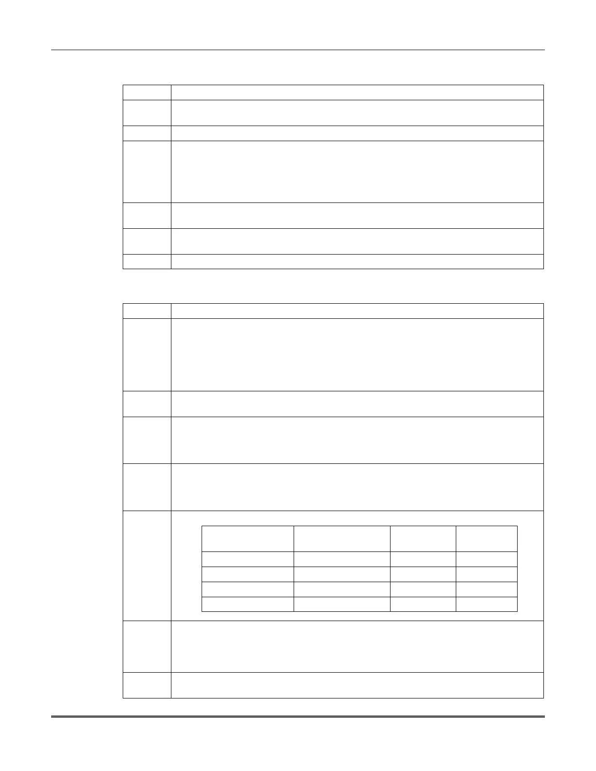
5 Connect the RS-485 bus cable to the control unit (see table below).
Wire Gauge/Color Function RS-485 #1
Terminal
RS-485 #2
Terminal
#19 AWG Blue RS-485 17 21
#19 AWG Yellow RS-485 18 22
#16 AWG Red + 12 VDC 19 23
#16 AWG Black DC Return 20 24
6 Insert each branch receptacle onto the appropriate molex connector, observing the proper
positioning for the type of sensor connected.
•
Powered sensors use Pins 1-2-3-4.
•
Non-powered sensors use Pins 3-4-5-6.
7
Form the branch cable(s) around the strain relief posts and over the slotted branch cable
entry port(s), and depress so the cable is flush with the edge of the housing base.
 Loading...


