Section 10 – Access Control
10-9
Installing and Wiring the Electric Door Strike and Card/Key Reader (or Keylok)
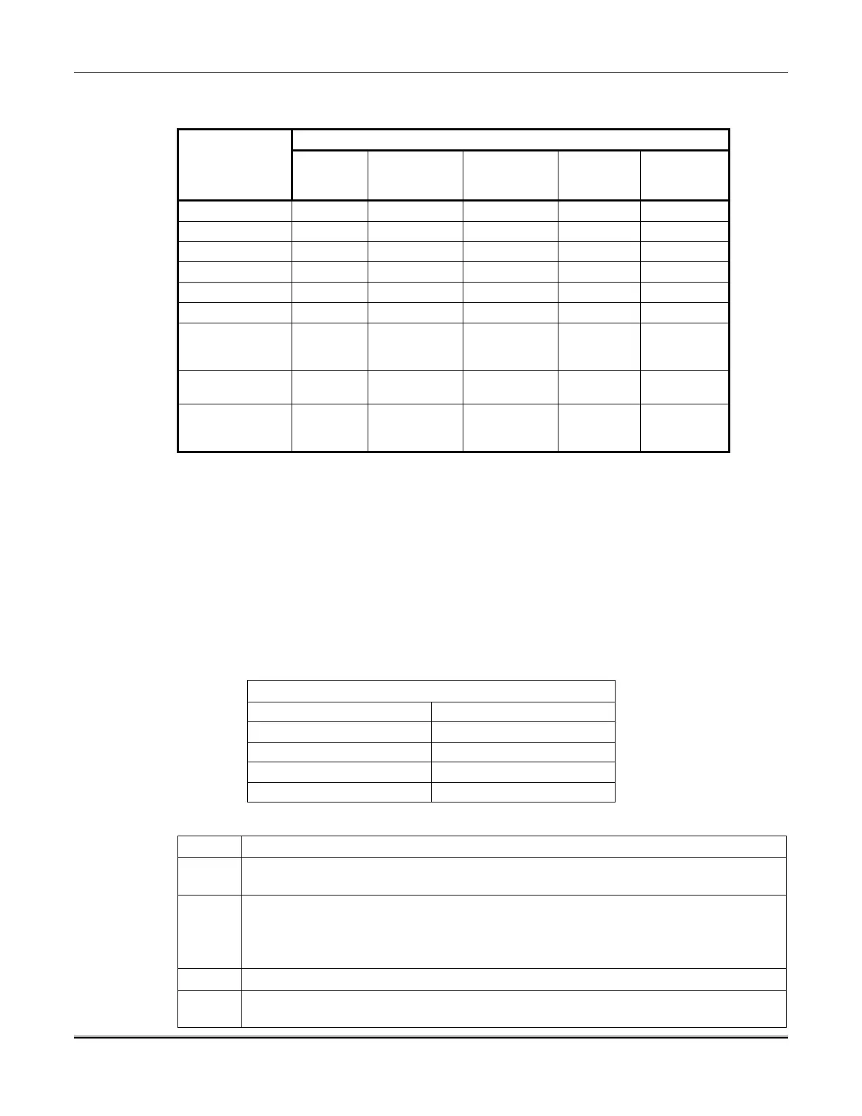
Wiring Connections Between ACIU and Readers/Strike
Reader and Strike Wire Connections (1)
ACIU Terminal
Marlok
Keylok (2)
Marlok
Keyreader
(2)
Sensor
Engineering
(Epic)
Dorado (5) Motorola
Indala
TB2-1 (-) (4) Brown Brown Black Black Black
TB2-2 (+)
Green Green Red Red Red
TB2-3 (data “0”)
Orange Orange Green Green Green
TB2-4 (data “1”)
Black Black White White White
TB2-5 (LED “A”)
Violet Brown Brown
TB2-6 (LED “B”)
Brown
NOT USED Blue
Orange
Yellow
Yellow
Blue
Orange
TB3-1 Strike (-) Red (2a)
Strike (-)
Strike (-) (3) Strike (-) (3) Strike (-) (3)
TB3-2 Strike (+)
Yellow (2a)
Strike (+)
Strike (+) (3) Strike (+) (3) Strike (+) (3)
(1) To extend reach of card/key readers for connection to ACIU, use manufacturer’s extension cable or use 494461 Cable as noted
below.
(2) For Marlok applications:
a.
For a Marlok KEYLOK (comes with 5V internal solenoid), connect red and yellow keylok wires to TB3-1 and TB3-2,
respectively, and remove Jumper E11 in order to supply 5V to solenoid.
b.
For Marlok KEYREADER (works with the 12V stand-alone strike):
1.
Connect (+) and (-) terminals of strike to TB3-2 and TB3-1, respectively.
2.
Insert a 330-ohm +/- 5%, 1-watt resistor in series with the yellow wire from Keyreader to TB3-2.
3.
Connect red wire from Keyreader directly to TB3-1.
4.
Insert Jumper E11 to supply 12V.
(3) Strike requires 12VDC (E11 = IN). If not using strike, connect a 3K resistor across TB3-1 and TB3-2.
(4) Connect TB2-1 to CWG so that wire from reader will be returned to CWG.
(5) Cut resistor R8 on the ACIU circuit board, if you are using Dorado 7401 or 7901 card readers. See
Figure 10-4.
Using 494461 (6466-10) Cable for Extension
1 BLK 6—BRN
2 RED 7—RED/BLK = Violet
3 BLU 8—BLU/BLK = Green
4 ORG 9—YEL/BLK = White
5 YEL 10—ORG/BLK
To install the electric door strike and card/key reader or Keylok, perform the following steps:
Step Action
1 Install the electric door strike and the card/key reader or Keylok in accordance with the
manufacturer's instructions.
2 Run the wiring in accordance with manufacturer's instructions, making sure that all
wiring to the ACIU does not exceed 150' (see
Figures 10-2 and 10-3
)
.
Where vendor extension cables are not available for the connections, use 494461 (6466-10)
Cable for the extension.
3 Set the DIP switch settings for the card reader, as required.
4 If you are not using a strike or a Keylok, install a standard 3K EOL resistor across TB3-1
and TB3-2 on the ACIU to simulate the strike load for the strike supervisory circuit.
 Loading...


