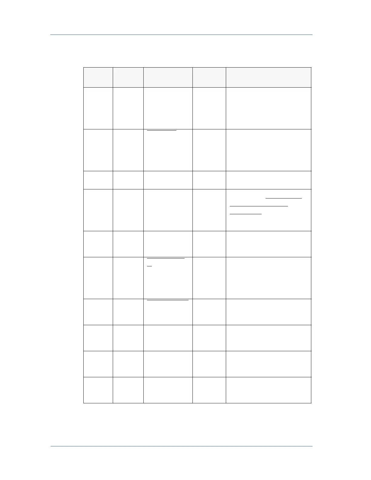
4-4 I/O Communication and Control 5702269-C
Advanced Energy
®
6
n/a COM.A n/a This signal is used as a
remote ground. VOUT.A (pin
2), POUT.A (pin 3), and
XPROG.A (pin 5) should be
referenced to this pin.
7
8 PWRON.D
digital
output
When output power is
enabled, a contact closure
between pin 7 and pin 8
occurs. Use 0.5 A maximum
for this readback.
8
n/a PWRON
COM.D
n/a This signal is the return for
pin 7.
9
n/a OUT ENABLE
COM.D
n/a This signal is the return
reference for SETPOINT.D
,
OUTPUT ENABLE.D
, and
OUTPUT.D
(pins 1, 4, and
13).
10
n/a MOD GREEN Output This pin is the emitter side of
an opto-coupler (for MOD
LED).
11
12 INTERLOCK.
D
Input This digital signal provides a
safety interlock. Closure
between pins 11 and 12
enables the ac input power
contactor.
12
n/a INTLK COM.D
n/a This signal is the return
reference for the interlock
signal on pin 11.
13
n/a NET GREEN Output This pin is the emitter side of
an opto-coupler (for NET
LED).
14
n/a MOD AMBER Output This pin is the emitter side of
an opto-coupler (for the
MOD LED).
15
n/a NET AMBER Output This pin is the emitter side of
an opto-coupler (for the NET
LED).
Table 4-1. User Port Pin Descriptions (Continued)
Signal
Pin
Return
Pin
Pin Name Signal
Type
Description