4-10 I/O Communication and Control 5702269-C
Advanced Energy
®
The scaling for power output is 0 to 10 V, where 10 V = the full rated output power
capability of the Pinnacle Plus+ power system (master and slave units). The read back
is limited to 10 V (0FFF
hex
), even in those cases where output may temporarily exceed
the maximum output capability of the power system.
The scaling for voltage output is 0 to 10 V, with 10 V = 1,000 V. The read back is
limited to 10 V (0FFF
hex
), even in those cases where output may temporarily exceed
1,000 V.
The scaling for current output is 0 to 10 V, with 10 V = the maximum output current
capability of the unit. The read back is limited to 10 V (0FFF
hex
), even in those cases
where output may temporarily exceed the maximum output current capability.
EXPLICIT MESSAGING
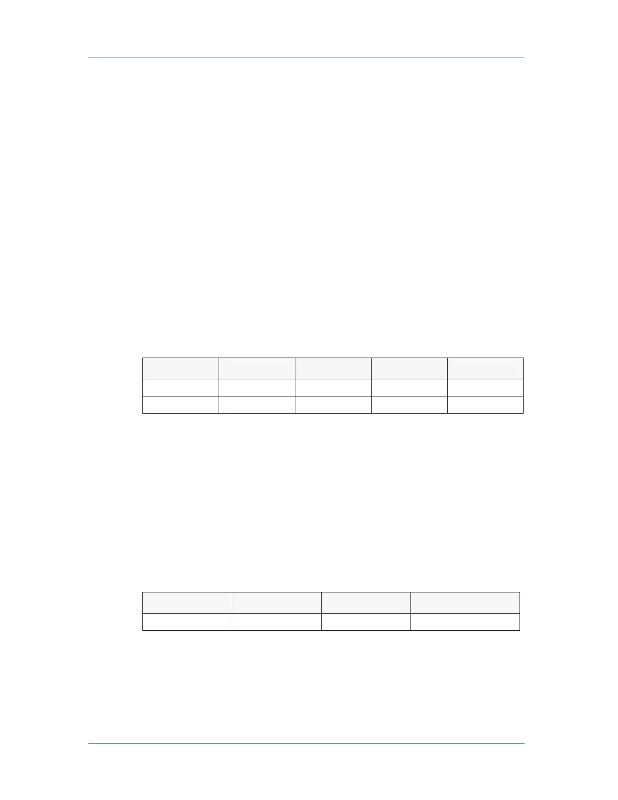
The Pinnacle Plus+ DeviceNet interface supports explicit messaging so that you can
receive information about two power system parameters: maximum power and
maximum current. Use the following Class Code 64 (40
hex
), Instance 1 attributes to
retrieve this information:
Note: The Max Power attribute returns a value in Watts if the unit is operating stand
alone. For example, a value of 20,000 equates to 20,000 W. The Max Power
attribute scaling is Watts x 10 if the unit is operating as a master/slave set. In
this case, a value of 2,000 equates to 20,000 W.
Note: The Max Current attribute returns a value in Amperes with 2 decimal places
implied. For example, a value of 8,000 equates to 80 A.
For more information about this type of messaging, refer to section 4-2 of the
DeviceNet Specification (version 2.0 or later). The following Common Services
specifications apply:
Rear Panel LEDs
The rear panel of the Pinnacle Plus+ unit features two bi-color LEDs (see Figure 4-3).
One is labeled MOD and indicates module status. The other is labeled NET and
indicates network status.
Attribute Access Name Type Value
6Get Max PowerUINT (1)
7 Get Max Current UINT (2)
Service Code Class Instance Service Name
14 (0E
hex
) Yes Yes Get_Attribute_Single