5702269-C I/O Communication and Control 4-9
Pinnacle™ Plus+ 10 kW
Ramping
The Pinnacle Plus+ unit examines the ramping-to-set point rate only if the output
power set point has been set to a new value. Ramping will begin again at 0 after an
off-on sequence has occurred.
RESPONSE MESSAGE
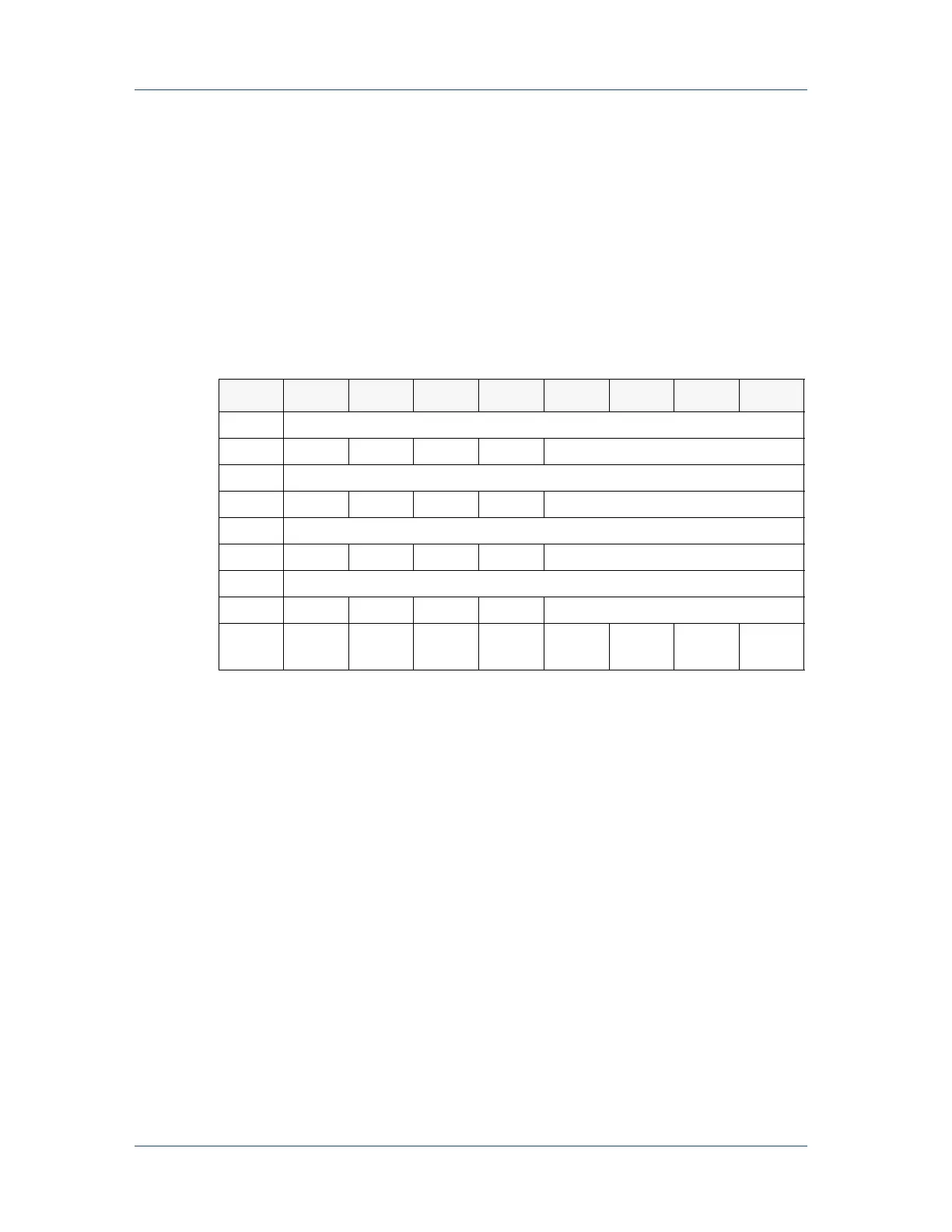
The following table represents the structure of the response message.
Note: The 16-bit Power Output value (AI) is shifted right four bits, and the remaining
four bits are filled with 0s. This changes the 16-bit AI to a 12-bit AI with a
value of 10 V = OFFF
hex
.
Note: For Byte 8, the abbreviations have the following meanings:
• POS stands for Power On Status: 1 = output on; 0 = output off
• SPS stands for Set Point Status: 1 = set point reached; 0 = set point not
reached
• TS stands for Temperature Status: 1 = good; 0 = over-temperature
condition
• ARCD stands for Arc Detected: 1 = on; 0 = off
• INTS stands for Interlock Status: 1 = satisfied; 0 = open
Scaling
Parts of the Message structure are based on binary representation of analog voltages.
Thus they have analog scaling associated with them.
Table 4-4. Structure of the poll command message
Byte Bit 7 Bit 6 Bit 5 Bit 4 Bit 3 Bit 2 Bit 1 Bit 0
0 Power Output AI (LSB)
1 0* 0* 0* 0* Power Output AI (MSB)
2 Voltage Output AI (LSB)
3 0* 0* 0* 0* Voltage Output AI (MSB)
4 Current Output AI (LSB)
5 0* 0* 0* 0* Current Output AI (MSB)
6 Ramp Rate Set Point AI (LSB)
7 0* 0* 0* 0* Ramp Rate Set Point AI (MSB)
8INTSARC
D
TS SPS POS