ELECTRICAL
9-3
GENERAL INFORMATION
ELECTRICAL SYSTEM SERVICE NOTES
Reference the following notes when diagnosing electrical
problems.
• Refer to wiring diagram for stator and electrical
component resistance specifications.
• When measuring resistance of a component that has a low
resistance value (under 10 Ohms), remember to subtract
meter lead resistance from the reading.
Connect the leads together and record the resistance.
The resistance of the component is equal to tested value
minus the lead resistance.
• Become familiar with the operation of the meter. Be sure
leads are in the proper jack for the test being
10A jack for current readings). Refer to
included with the meter for more information.
• Voltage, amperage, and resistance values included in this
manual are obtained with a Fluke™ 77 Digital Multi-
This meter is acceptable for use when diagnosing electrical
problems. Readings obtained with other meters may differ.
• Pay attention to the prefix on the multi-meter reading (K,
M, etc.) and the position of the decimal point.
• For resistance readings, isolate the component to be
tested. Disconnect it from the wiring harness or power
supply.
WIRE COLOR LETTER LIST
Letter Color Letter Color
B Black L/Y Blue/Yellow
B/L Black/Blue O Orange
Br Brown O/B Orange/Black
B/R Black/Red P Pink
Br/L Brown/Blue Pu Purple
Br/W Brown/White R Red
B/Y Black/Yellow R/B Red/Black
C Cyan R/W Red/White
DB Deep Brown W White
DG Deep Green WB Water Blue
G Green W/B White/Black
Gr Gray W/L White/Blue
G/R Green/Red W/R White/Red
G/W Green/White Y Yellow
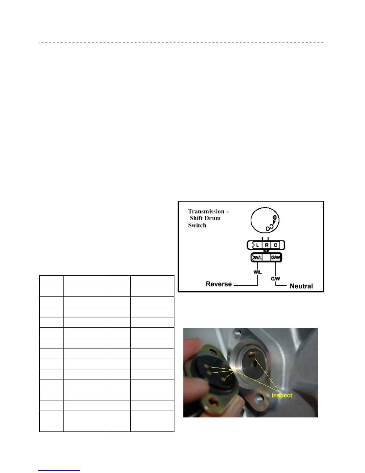
TRANSMISSION SWITCH SERVICE
Switch Removal/Test
1. Remove the CVT cover. The indicator switch will be visible
between the drive and driven clutch.
Refer to Chapter 3 for CVT cover removal and install.
2. Remove the screws that retain the indicator switch.
3. Using an ohmmeter, test for continuity between the switch
contacts and connector leads. Replace the switch if no continuity
or high resistance is found.
4. First, shift the transmission into “neutral” and test for
between the G/W wires and ground.
5. Then shift the transmission into “reverse” and test for
continuity between the W/L wires and ground. In both tests you
should have continuity to ground.
6. Inspect the shift indicator contacts, shift drum, pin and spring.
Verify the pin is not sticking in the drum or is damaged. Replace
any worn or damaged components.

 Loading...