ENGINE
4-35
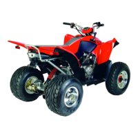
3. The connecting rod utilizes a roller bearing. Clearance is
minimal and cannot be measured. Visually inspect bearing
journal for scoring, damage or excessive wear. Replace
crankshaft if it fails visual inspection.
CRANKCASE / BEARING INSPECTION
NOTE: Removal and installation of new seals is
recommended anytime the crankcase is
disassembled.
1. Inspect the bearings in the crankcase.
NOTE: Due to extremely close tolerances and
minimal side wear, the bearing must be inspected
visually and by feel. Look for signs of discoloration,
scoring or galling. Turn the inner race of bearing. The
bearing should turn smoothly and quietly. The outer
race should fit tightly in the crankcase. The inner
race should be firm with minimal side-to-side
movement and no detectable up and down
movement.
2. To remove crankcase bearings, use a blind hole bearing
puller.
NOTE: Bearings are stressed during the removal
procedure and should not be re-used.
3. Remove all traces of gasket sealer from the crankcase
mating surfaces. Inspect the surfaces closely for nicks, burrs or
damage.
CRANKCASE OIL STRAINER INSPECTION
1. Remove drain plug.
2. Remove oil strainer and visually inspect for any rips, tears
or obstructions in screen.
3. Replace oil strainer if it fails visual inspection.
BEARING /SEAL INSTALLATION
NOTE: To ease crankcase-bearing installation, warm
the crankcase until hot to the touch. Placing the
bearing in a freezer prior to installation will assist the
assembly process.
1. Install the bearing so the numbers are visible.
2. Drive or press the new bearing into the crankcase, using the
proper driver.
CAUTION
Press only on outer race of bearing to prevent
bearing damage.
3. Install new seals with the lip facing in.
CAUTION
Press only on outer diameter to prevent damage.
4. Inspect the clearance of connecting rod big end and flywheel
by feeling gauge. If clearance is excessive replace the
crankshaft assembly.
CONNECTING ROD CLEARANCE LIMITATION:
0.5 mm
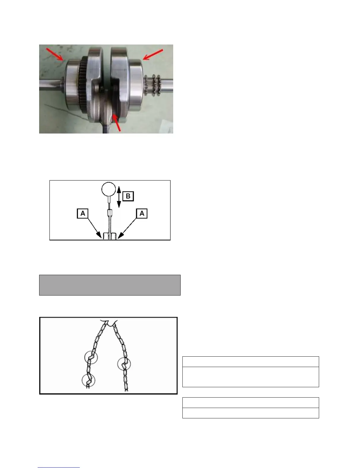
5. Inspect chain for worn or missing rollers or damage.
Replace if worn excessively or as part of any crankshaft repair.

 Loading...