ELECTRICAL
9-4
SWITCH SERVICE
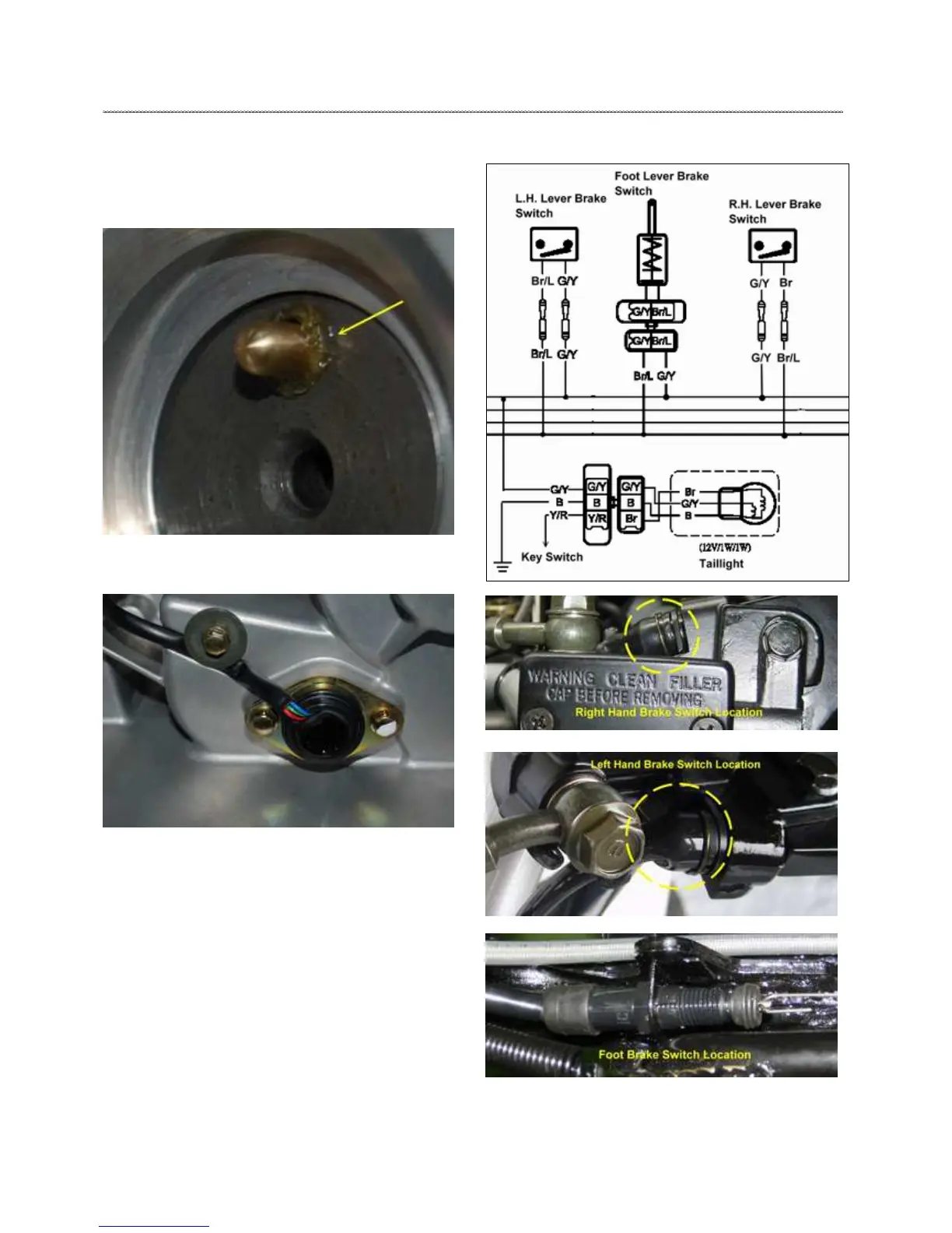
Switch Installation
1. Once repairs are completed, reinstall the shift pin and spring
into the shift drum (arrow). NOTE: assembly lube can be used
to “stick” parts together for ease of assembly.
2. Install the indicator switch and o--ring (arrow), routing the
wires in the same manner as during disassembly.
3. Install the retaining screws. Torque to 5Nm (45 in. lbs).
BRAKE LEVER SWITCH
Each brake lever utilizes an electrical brake switch that sends
voltage to activate the brake light.
1. Locate the brake switches on each of the brake levers.
2. Disconnect wire harness from brake switch and connect an
ohmmeter across the two switch wires.
The reading should be infinite (•).
3. To act the brake lever(s) and check for continuity between
switch contacts. Replace switch if there is no continuity or if the
resistance is greater than .5 ohms when the brake is applied with
slight pressure.

 Loading...