ELECTRICAL
9-13
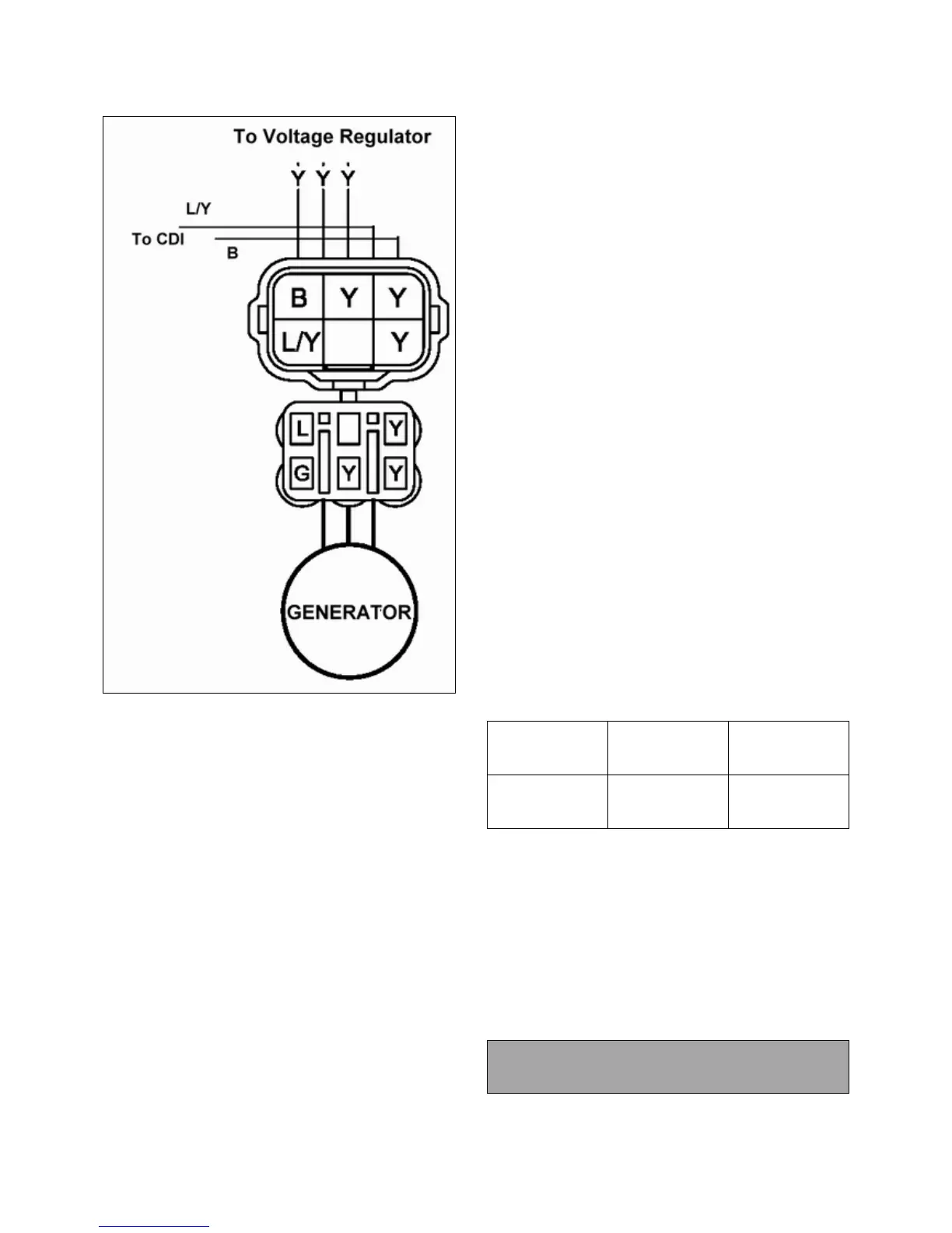
TEST 1: Resistance Value of Each Stator coupler
1. Measure the resistance value of each stator coupler for three:
Y1 to Y2, Y1 to Y3, and Y2 to Y3.
Each should measure 0.7--1.0 ohms
2. When measuring any of the Yellow wires to ground, the
reading should be infinite (open).
NOTE: If there are any significant variations in ohm’s
readings between the three couplers,
that one of stator coupler maybe weak or failed.
TEST 2:Resistance Value of Stator coupler to Ground
1. Measure the resistance value of each of the stator coupler to
ground: Y1 to Ground, Y2 to Ground, and Y3 to Ground.
NOTE: Any measurement other than Infinity (open)
indicate a failed or shorted stator coupler.
TEST 3: Measure AC Voltage Output of Each
Stator coupler at Charging RPM with a voltmeter set
to Volts AC.
1. Place the red lead on the tester in the 10A jack.
2. Turn the selector dial to the Volts AC position.
3. Start the engine and let it idle.
4. Separately test each ’leg’ of the stator by connecting the
meter leads to the wires leading from the alternator (Y1 to
Y2, Y1 to Y3, Y2 to Y3).
Alternator Current Output Reading should be no less than
30--40V AC above 2000 RPM on each coupler.
NOTE: If one or more of the stator leg output AC
voltage varies significantly from the specified value,
the stator may need to be replaced.
CDI OUTPUT TEST USING PEAK READING
ADAPTOR OR A VOLT METER
Re-connect all CDI wires to stator wires. Disconnect
CDI module wire from ignition coil primary terminal.
Connect one meter lead to engine ground and the other to the
ignition coil primary wire leading from the
CDI module. Crank engine and check output of CDI wire to
coil. Reconnect coil wire to CDI.
Test Connect meter
wire to:
Reading
CDI output
B/Y to
Engine Ground
240DC Volts ±
20%
CDI OUTPUT TEST USING PEAK READING
ADAPTOR
Re-connect all CDI wires to stator wires. Disconnect
CDI module wire from ignition coil primary terminal.
Connect one meter lead to engine ground and the other to the
ignition coil primary wire leading from the
CDI module. Set meter to read DC Volts. Crank
engine and check output of CDI wire to coil.
Average Output w/ Digital Voltmeter
20 DCV

 Loading...