ELECTRICAL
9-5
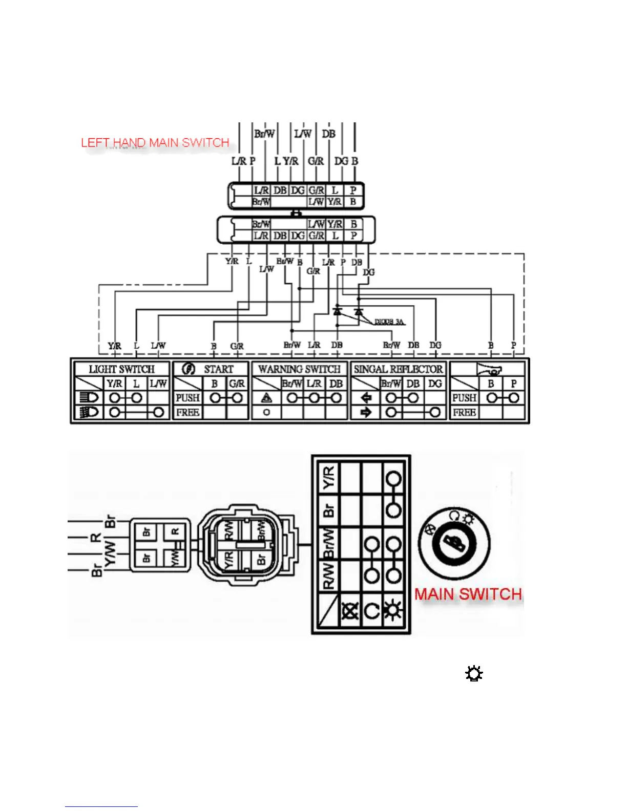
LEFT HAND SWITCH ASSEMBLY
The following illustration shows the internal operation of the
LH switch assembly. If any part of the switch is faulty, the entire LH switch assembly must be replaced.
KEY SWITCH
The key switch can be tested with an ohmmeter.
When the key switch is turned to the “ON” position, there
should be continuity between the red/whore (R/W) and
brown/white (Br/W) wires.
When the key is turned to the “OFF” position, there should no
continuity between any of the wires.
When the key switch is turned to the “ ” position, there
should be continuity between the red/whore (R/W) and
brown/white (Br/W) wires. There should also be continuity
between the brown (Br) and yellow/red (Y/R) wires.

 Loading...