CVT SYSTEM
3-10
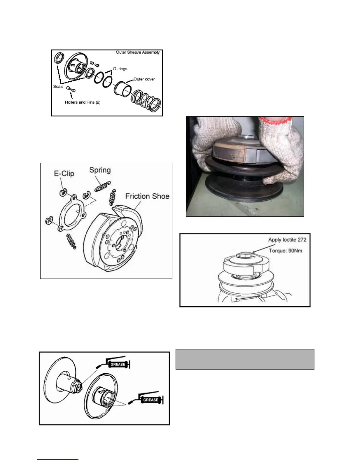
6. To replace the friction shoes, remove the e—clips that
retain the backing plate. Use a suitable tool to remove and
install the springs connecting the shoes, using care not to
over--stretch the springs more than is necessary.
DRIVEN CLUTCH ASSEMBLY
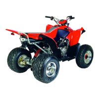
1. Insert new seals into the outer sheave assembly. Fill the
outer sheave cavity with fresh grease and slide onto the inner
sheave shaft. Align and insert the roller/pin assemblies.
Install new o-rings and the outer roller pin cover. Place the
washer onto the threaded shaft and apply Loctite 272 to the
threads.
2. Have an assistant available for final assembly.
Install the compression spring. Place the friction pad assembly
over the spring and compress the driven assembly together
with both hands. With the assembly compressed and the
threads exposed, have an assistant thread a new retaining nut
onto the shaft. Secure the assembly in a clamping device and
torque the retaining nut to 90 Nm.
NOTE: Outer sheave retaining nut replacement is strongly
recommended. Use Loctite 272 on the threads during
reassembly.
Driven Assembly Nut Torque
90 Nm (67 ft. lbs.)

 Loading...