Troubleshooting Procedure
1. Remove all remote I/O connections and front panel connections to the instrument. Verify that:
a. the AC mains power cord is securely connected to the instrument and plugged into a live outlet
b. the front-panel Power On/Standby switch has been pushed
2. If the standby light below the power switch is not illuminated, re-verify the items above. If all this is correct, check
the AC mains power and then the internal line fuse.
3. If the standby light is on (yellow or green), press the power button. If there is no response, replace the front-panel
board because the power button on the front-panel board is likely broken.
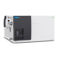
4. Check the voltages on the power supply. If one or more of these tests fail, disconnect the transformer secondaries
from the main board and measure the voltages from the transformer with an AC voltmeter.
The voltage between the red and orange wires (below)should measure 7.5 to 11 VAC.
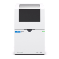
The voltage between the brown and white wires (below) should measure 11 to 15 VAC.
5. If the voltages are correct, replace the main board; otherwise replace the transformer.
6. Turn the instrument on. If the power-on sequence completes and the display appears to function properly, verify
that the instrument is in local mode (the Remote annunciator in the upper right corner of the display is not on),
and run the full self-test ([Utility] > Test/Admin > Self-Test > Full Test). If the display is illegible, replace
the front-panel board.
Ensure that all connections (front and rear) are removed when self-test is performed. During self-
test, errors may be induced by signals present on external wiring, such as long test leads that can
act as antennas.
294 Agilent Truevolt Series DMM Operating and Service Guide
 Loading...