High Voltage Self-Heating Errors
If you apply more than 300 Vrms, self–heating occurs in the multimeter's internal signal–conditioning components.
These errors are included in the multimeter's specifications. Temperature changes inside the multimeter due to self–
heating may cause additional error on other AC voltage ranges. The additional error is less than 0.02% and dissipates
in a few minutes.
AC Current Measurement Errors (Burden Voltage)
Burden voltage errors, which apply to DC current, also apply to AC current measurements. However, the burden
voltage for AC current is larger due to the multimeter's series inductance and your measurement connections. The
burden voltage increases as the input frequency increases. Some circuits may oscillate when performing current
measurements due to the multimeter's series inductance and your measurement connections.
Low–Level Measurement Errors
AC voltage measurements less than 100 mV are especially susceptible to errors introduced by extraneous noise
sources. An exposed test lead acts as an antenna and a properly functioning DMM will measure the signals received.
The entire measurement path, including the power line, act as a loop antenna. Circulating currents in the loop create
error voltages across any impedances in series with the DMM's input. Therefore, you should apply low–level AC voltages
to the DMM through shielded cables, with the shield connected to the input LO terminal.
Connect the DMM and the AC source to the same electrical outlet whenever possible. You should also minimize the
area of any ground loops that cannot be avoided. A high–impedance source is more susceptible to noise pickup than a
low–impedance source. You can reduce the high–frequency impedance of a source by placing a capacitor in parallel
with the DMM's input terminals. You may have to experiment to determine the correct capacitor for your application.
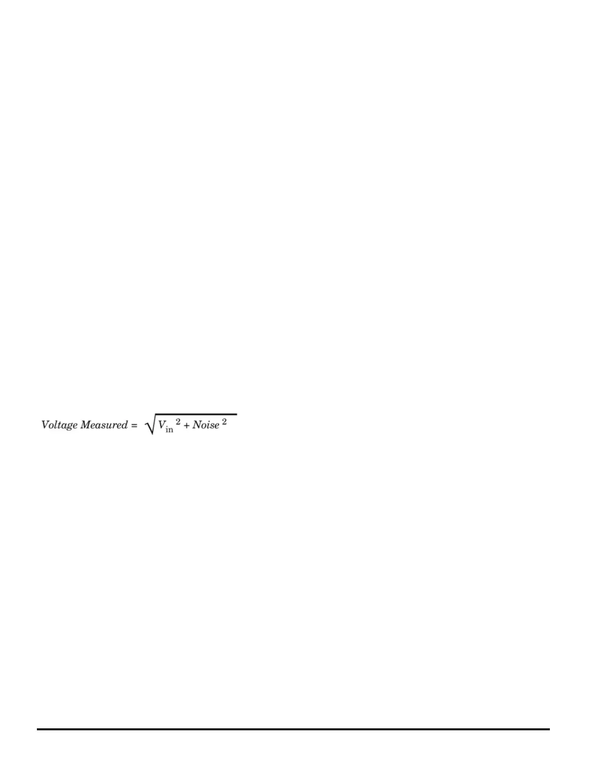
Most extraneous noise is not correlated with the input signal. You can determine the error as shown below.
Correlated noise, while rare, is especially detrimental because it always adds directly to the input signal. Measuring a
low–level signal with the same frequency as the local power line is a common situation that is prone to this error.
Common Mode Errors
Errors are generated when the multimeter's input LO terminal is driven with an AC voltage relative to earth. The most
common situation where unnecessary common mode voltages are created is when the output of an AC calibrator is
connected to the multimeter "backwards." Ideally, a multimeter reads the same regardless of how the source is
connected. Both source and multimeter effects can degrade this ideal situation. Because of the capacitance between
the input LO terminal and earth (approximately 200 pF), the source will experience different loading depending on how
the input is applied. The magnitude of the error is dependent upon the source's response to this loading.
The DMM's measurement circuitry, while extensively shielded, responds differently in the backward input case due to
slight differences in stray capacitance to earth. The DMM's errors are greatest for high–voltage, high–frequency inputs.
Typically, the DMM exhibits about 0.06% additional error for a 100 V, 100 kHz reverse input. You can use the
grounding techniques described for DC common mode problems to minimize AC common mode voltages.
98 Agilent Truevolt Series DMM Operating and Service Guide
 Loading...