Rockwell Automation Publication 750-IN001P-EN-P - April 2017 103
Lift and Mount the Drive Chapter 3
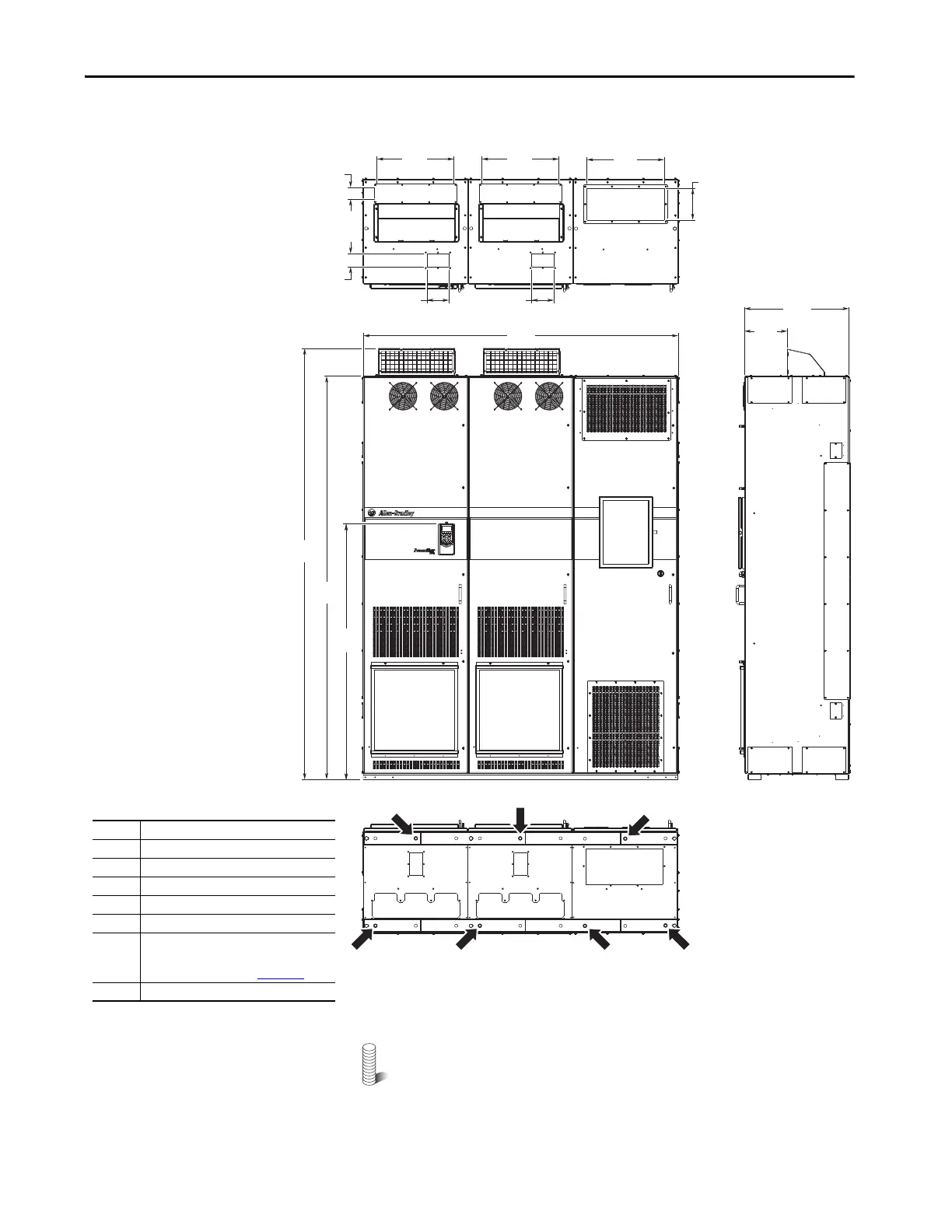
Figure 67 - IP20, NEMA/UL Type 1, MCC Style Cabinet, Floor Mount Frame 9
(Enclosure Code B with P14)
M12 (1/2 in.) Property Class 8.8 anchor hardware is recommended
to fasten the drive cabinet through its internal mounting angle to the
foundation. Anchor bolts can be pre-located and embedded in the
foundation before instillation.
600
(23.6)
240
(9.4)
440
(17.3)
440
(17.3)
127
(5.0)
440
(17.3)
127
(5.0)
76
(3.0)
1
1
1
2
3
4
5
6
7
2
68
(2.7)
2453
(96.6)
2300
(90.6)
1464
(57.6)
1800
(70.9)
180
(7.1)
No. Description
1 Power wiring conduit plates.
2 Control wiring conduit plates.
3 Optional exhaust hood.
4 Optional HIM.
5 Option bay disconnect switch access door.
6 Interlock override switch.
For instructions and precautions see the
Hardware Service Manual, 750-TG001
.
7 Recommended seven-hole anchoring.
Bottom
To p
600 mm (23.6 in.) Deep Drive with Cabinet
Options Bay
 Loading...

