Rockwell Automation Publication 750-IN001P-EN-P - April 2017 109
Lift and Mount the Drive Chapter 3
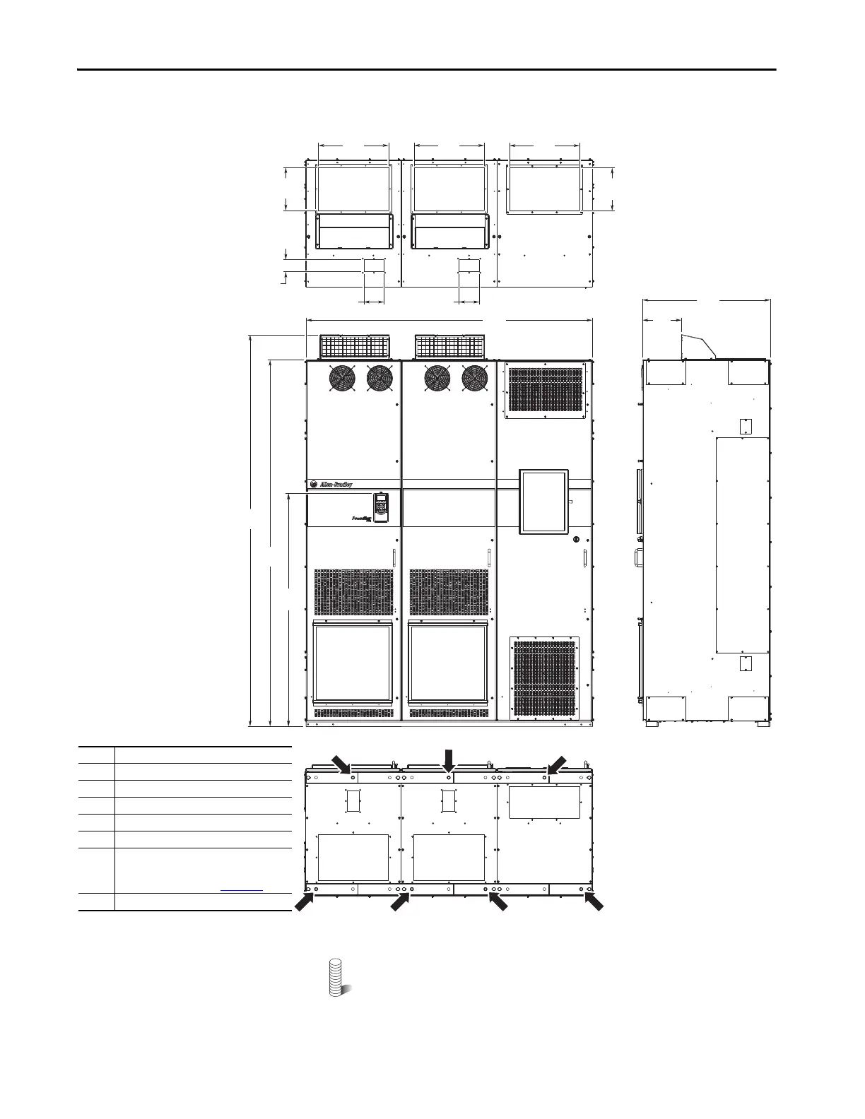
Figure 73 - IP20, NEMA/UL Type 1, MCC Style Cabinet, Floor Mount Frame 9
(Enclosure Code L, P, W)
M12 (1/2 in.) Property Class 8.8 anchor hardware is recommended
to fasten the drive cabinet through its internal mounting angle to the
foundation. Anchor bolts can be pre-located and embedded in the
foundation before instillation.
1800
(70.9)
440
(17.3)
440
(17.3)
2453
(96.6)
2300
(90.6)
800
(31.5)
240
(9.4)
440
(17.3)
270
(10.6)
270
(10.6)
1464
(57.6)
127
(5.0)
127
(5.0)
76
(3.0)
1
1
1
2
2
3
4
5
6
7
No. Description
1 Power wiring conduit plates.
2 Control wiring conduit plates.
3 Optional exhaust hood.
4 Optional HIM.
5 Option bay disconnect switch access door.
6 Interlock override switch.
For instructions and precautions see the
Hardware Service Manual, 750-TG001
.
7 Recommended seven-hole anchoring.
Bottom
To p
800 mm (31.5 in.) Deep Drive with
Cabinet Options Bay
 Loading...

