Rockwell Automation Publication 750-IN001P-EN-P - April 2017 117
Lift and Mount the Drive Chapter 3
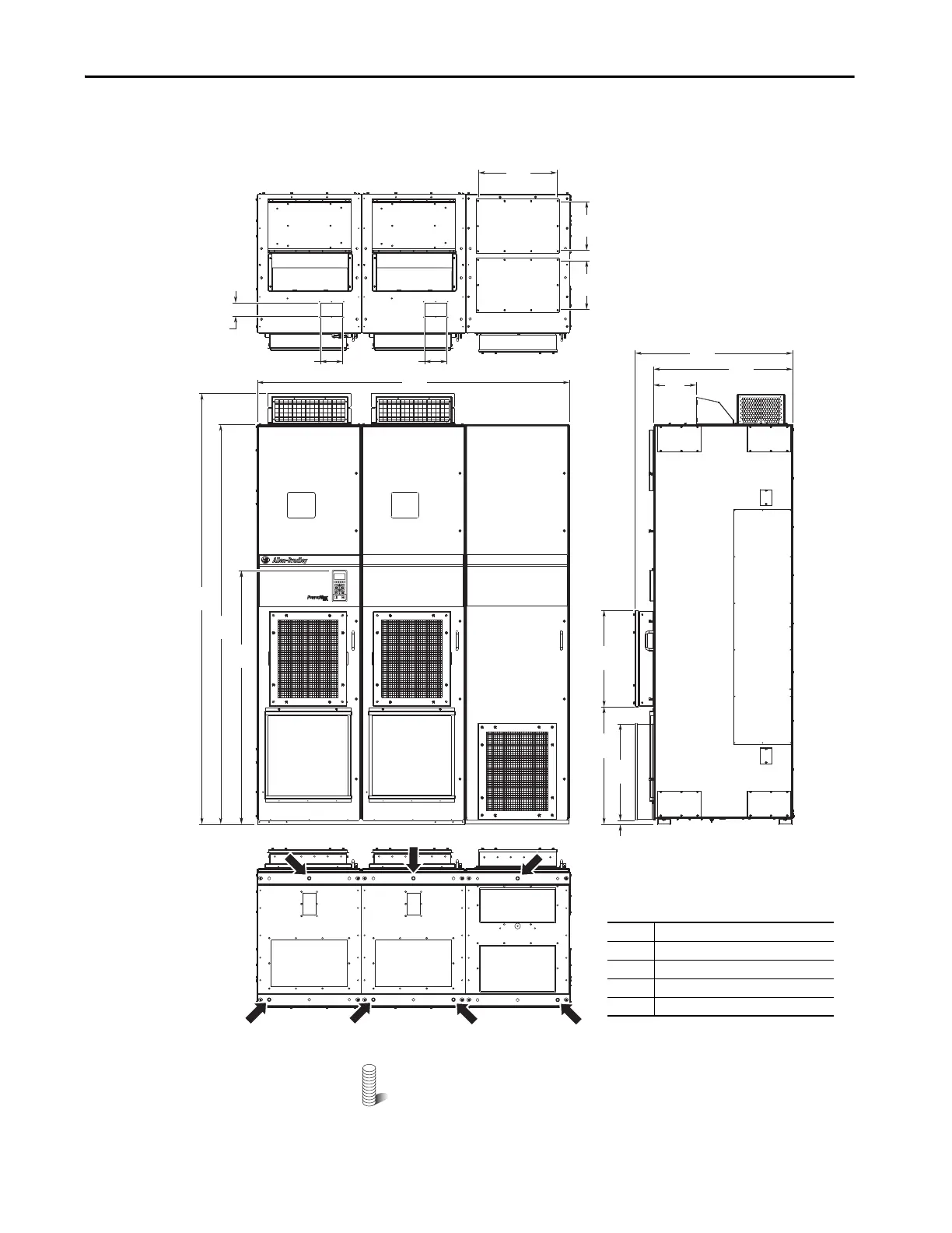
Figure 81 - IP54, NEMA 12, MCC Style Cabinet, Floor Mount Frame 9 (Enclosure Codes K and Y)
IP54, UL Type 12, MCC Style Cabinet, Floor Mount Frame 9 (Enclosure Code J)
With P14
M12 (1/2 in.) Property Class 8.8 anchor hardware is recommended
to fasten the drive cabinet through its internal mounting angle to the
foundation. Anchor bolts can be pre-located and embedded in the
foundation before instillation.
2477
(97.5)
2300
(90.6)
1800
(70.9)
1464
(57.6)
800
(31.5)
909
(35.8)
244
(9.6)
675
(26.6)
556
(21.9)
24
(1.0)
556
(21.9)
310
(12.2)
310
(12.2)
480
(18.9)
78
(3.1)
1
1
2
3
4
2
127
(5.0)
127
(5.0)
No. Description
1 Power wiring conduit plates.
2 Control wiring conduit plates.
3 Optional HIM.
4 Recommended seven-hole anchoring.
Top
800 mm (31.5 in.) Deep Drive with
Wiring Bay
 Loading...

