EasyManuals Logo
Home>Allen-Bradley>Controller>20F

Allen-Bradley 20F Installation Instructions

Allen-Bradley 20F
320 pages
To Next Page IconTo Next Page
To Previous Page IconTo Previous Page
Page #121 background imageLoading...
Page #121 background image
Rockwell Automation Publication 750-IN001P-EN-P - April 2017 121
Lift and Mount the Drive Chapter 3
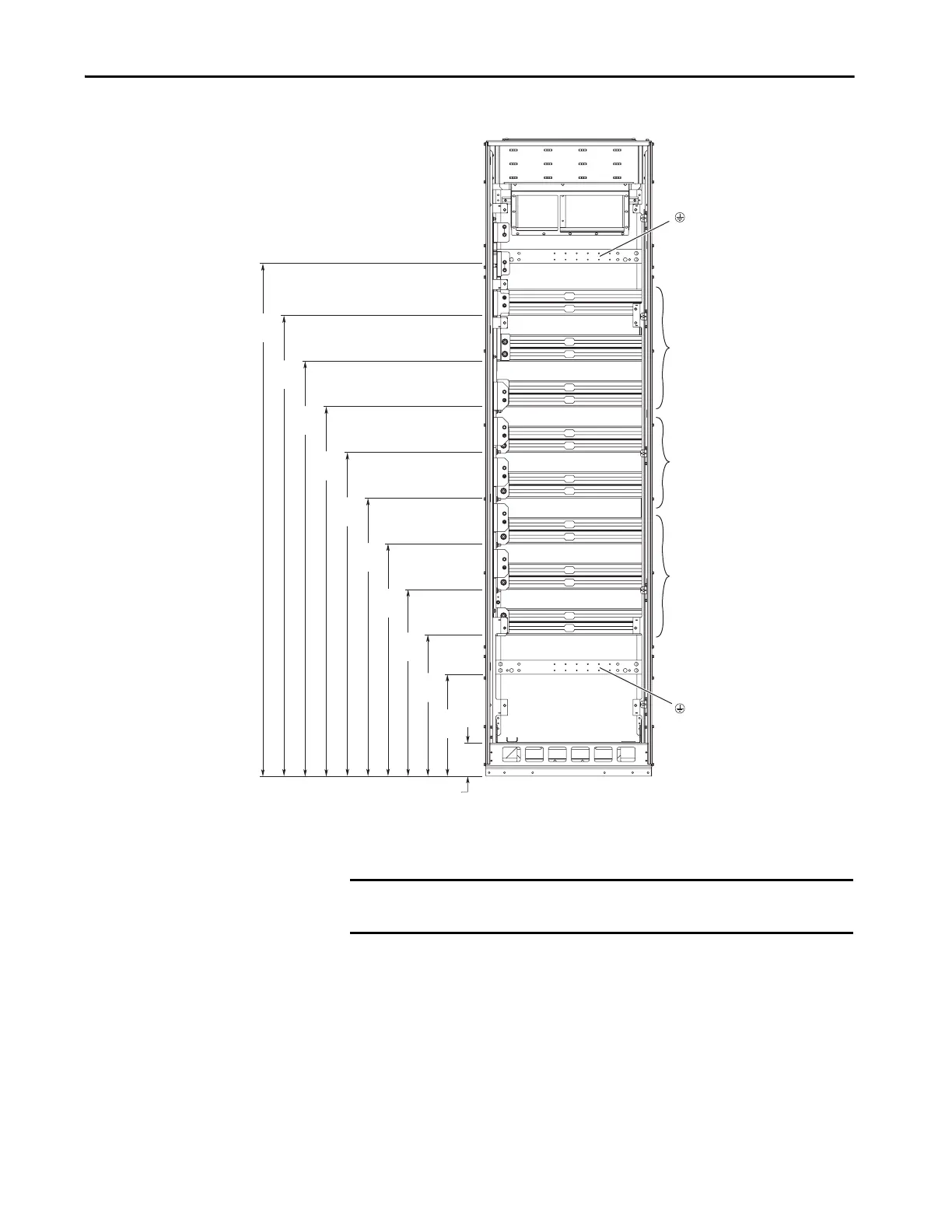
Figure 85 - Bus Bar Dimensions (AC Input)
Dimensions are in millimeters and (inches).
369
(14.5)
511
(20.1)
671
(26.4)
841
(33.1)
1006
(39.6)
1171
(46.1)
1336
(52.6)
1501
(59.1)
1666
(65.6)
1854
(73.0)
125
(4.9)
R / L1
S / L2
T / L3
DC+
DC-
U / T1
V / T2
W / T3
PE
PE
DC Bus Connection Kit (Catalog
Number 20-750-BUS1A-F8) Is
Required.
IMPORTANT To connect to the DC bus bars, a PowerFlex 750-Series DC bus connection kit
(catalog number 20-750-BUS1A-F8) is required.

Table of Contents

Other manuals for Allen-Bradley 20F

Questions and Answers:

Question and Answer IconNeed help?

Do you have a question about the Allen-Bradley 20F and is the answer not in the manual?

Allen-Bradley 20F Specifications

General IconGeneral
BrandAllen-Bradley
Model20F
CategoryController
LanguageEnglish

Related product manuals