Rockwell Automation Publication 750-IN001P-EN-P - April 2017 165
Power Wiring Chapter 4
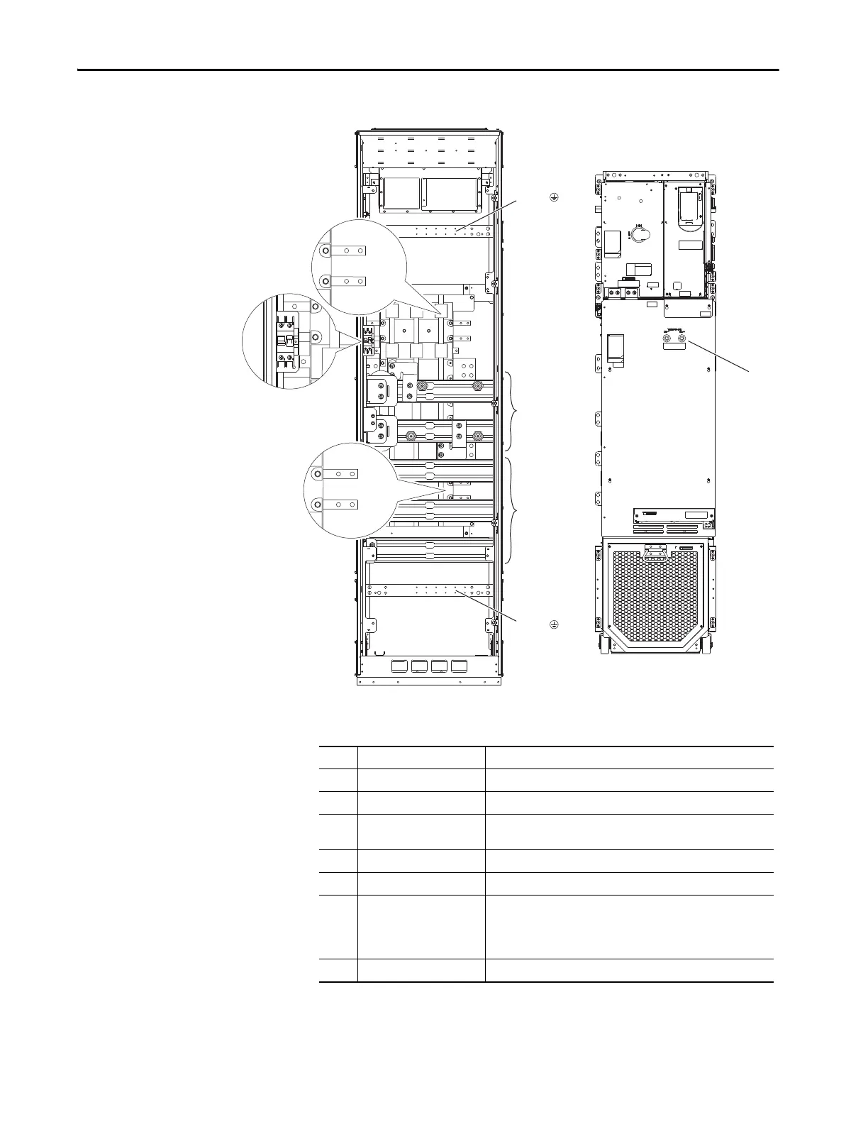
Figure 99 - Bus Bar and AC Power Rail Locations, Common DC Input Floor Mount Drives
Table 16 - Floor Mount Frame 8 Common DC Input
DC+
DC–
U / T1
V / T2
W / T3
PE
3
3
1
2
PE
4
6
7
5
Frame 8
Hot
Neutral
Hot
Neutral
No. Name Description
1 DC power bus DC+, DC-
2 Power bus U/T1, V/T2, W/T3
3 PE grounding bar Terminating point to chassis ground for incoming AC line and motor
shield.
4 Control rail 120V AC control power supply connections. Top rail is hot.
5 Control power circuit breaker 120V AC control power supply circuit breaker.
6 UPS rail 120V AC uninterruptible power supply (UPS) connections. Top rail is
hot.
The UPS rail is only installed when the P30 UPS control bus option is
selected.
7 DC+ and DC- Bus voltage test points
 Loading...

