202 Rockwell Automation Publication 750-IN001P-EN-P - April 2017
Chapter 4 Power Wiring
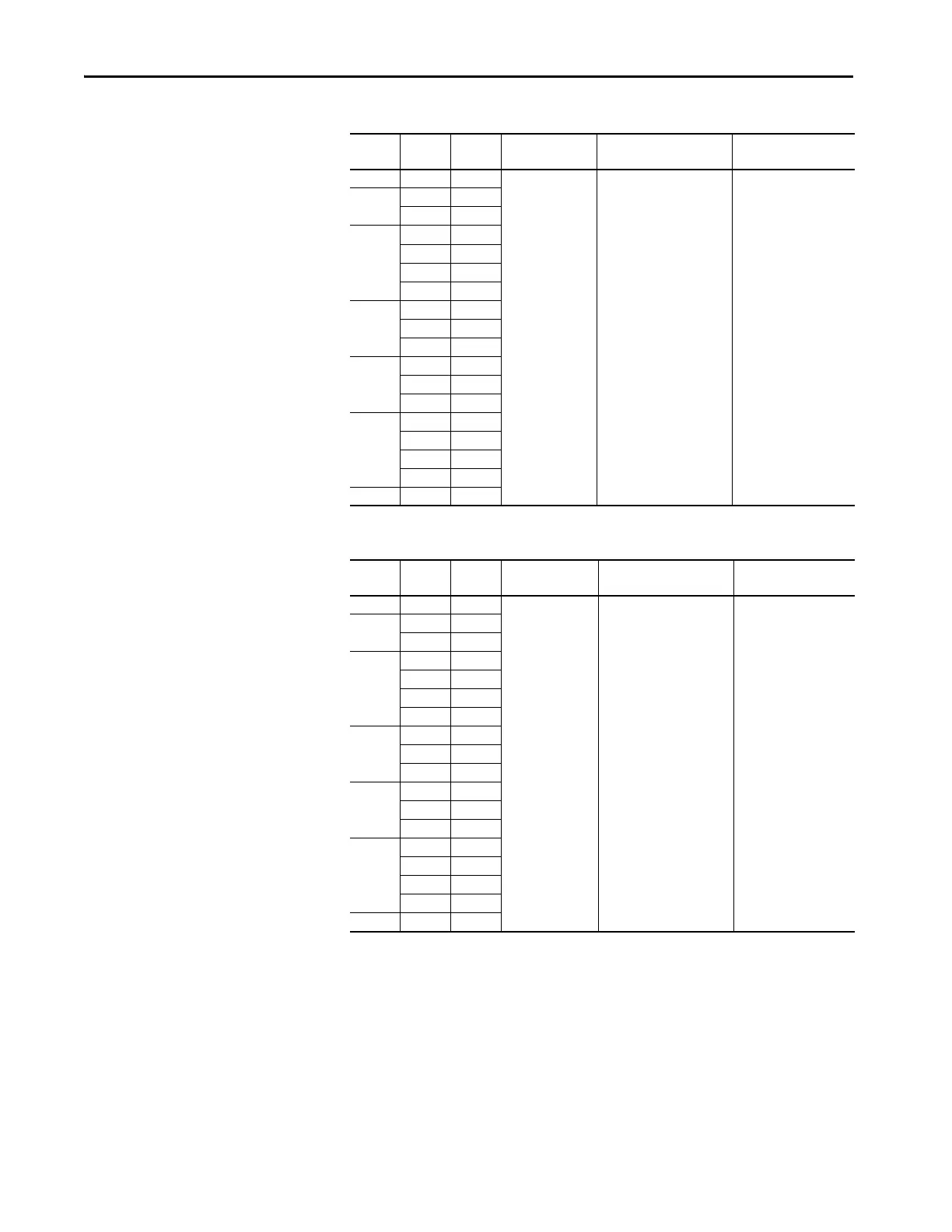
Table 35 - 600V, 50 Hz Input – Code P3 Thermal Magnetic Circuit Breaker Options
Table 36 - 600V, 50 Hz Input – Code P5 Molded Case Disconnect Switch Options (only floor
mount Frame 8)
Hp Amps Duty Line Side Terminal
Lugs
Terminal Size Recommended Torque
N•m (lb•in)
250 272 Heavy
140G-M-TLA23 (2) 250…500 MCM kit of 3 31 (274)
300
295 Heavy
295 Normal
350
329 Heavy
355 Heavy
355 Light
355 Normal
400
395 Heavy
395 Light
395 Normal
450
425 Heavy
435 Light
435 Normal
500
460 Light
460 Normal
510 Light
510 Normal
550 545 Light
 Loading...

