EasyManuals Logo
Home>Allen-Bradley>Controller>20F

Allen-Bradley 20F Installation Instructions

Allen-Bradley 20F
320 pages
To Next Page IconTo Next Page
To Previous Page IconTo Previous Page
Page #207 background imageLoading...
Page #207 background image
Rockwell Automation Publication 750-IN001P-EN-P - April 2017 207
Power Wiring Chapter 4
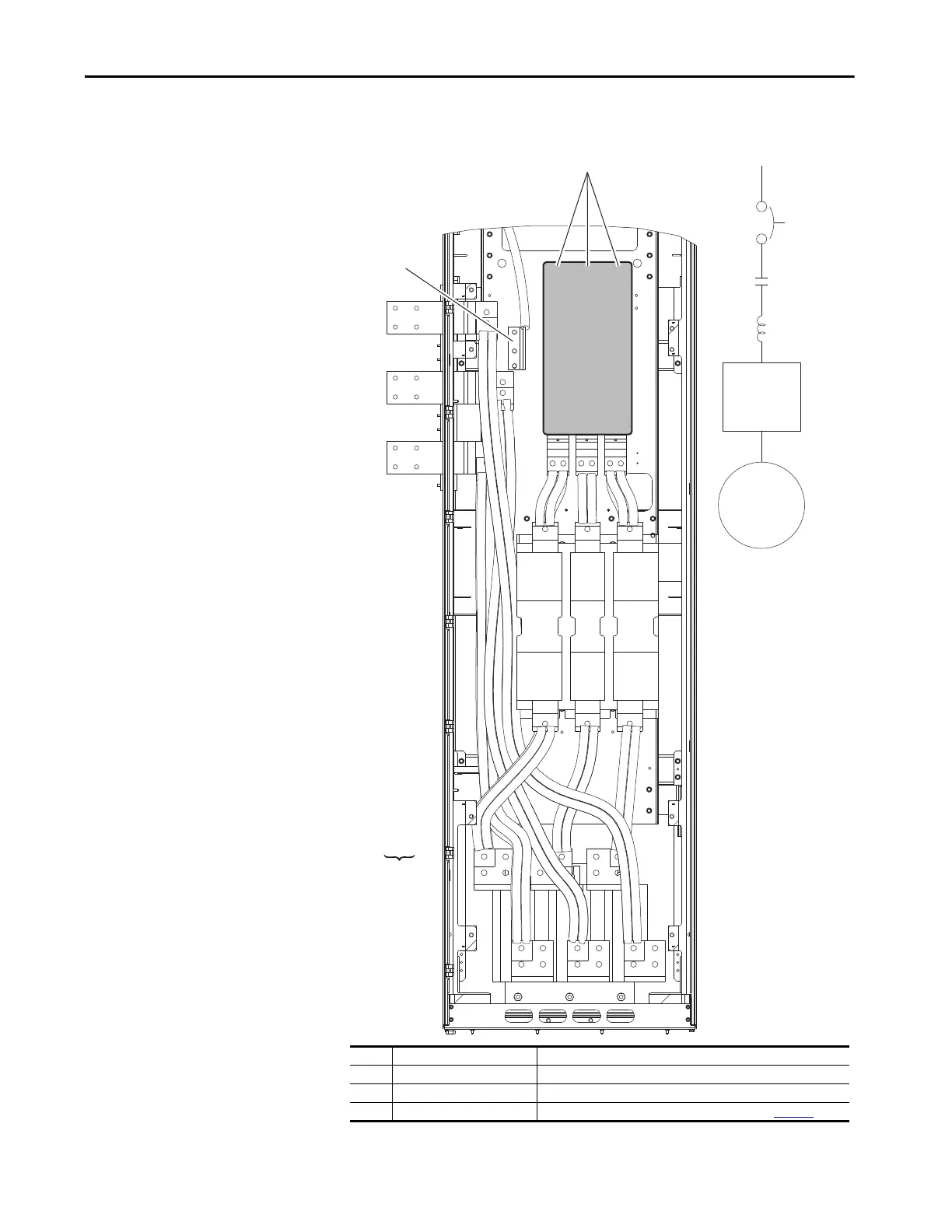
Figure 112 - Option P3 or P5 Disconnect, Option P11 Input Contactor, and Option L1 or L3 Input
Reactor (only floor mount Frame 8)
No. Name Description
1 R/L1, S/L2, T/L3 Three-phase input power connection.
2 PE Three-phase input ground.
3 U/T1, V/T2, W/T3 Motor connection that is made at drive power bus. See page 164
.
U / T1
V / T2
W / T3
3
2
1
Drive
Motor
P3 or P5
P11
L1 or L3

Table of Contents

Other manuals for Allen-Bradley 20F

Questions and Answers:

Question and Answer IconNeed help?

Do you have a question about the Allen-Bradley 20F and is the answer not in the manual?

Allen-Bradley 20F Specifications

General IconGeneral
BrandAllen-Bradley
Model20F
CategoryController
LanguageEnglish

Related product manuals