EasyManuals Logo
Home>Allen-Bradley>Controller>20F

Allen-Bradley 20F Installation Instructions

Allen-Bradley 20F
320 pages
To Next Page IconTo Next Page
To Previous Page IconTo Previous Page
Page #208 background imageLoading...
Page #208 background image
208 Rockwell Automation Publication 750-IN001P-EN-P - April 2017
Chapter 4 Power Wiring
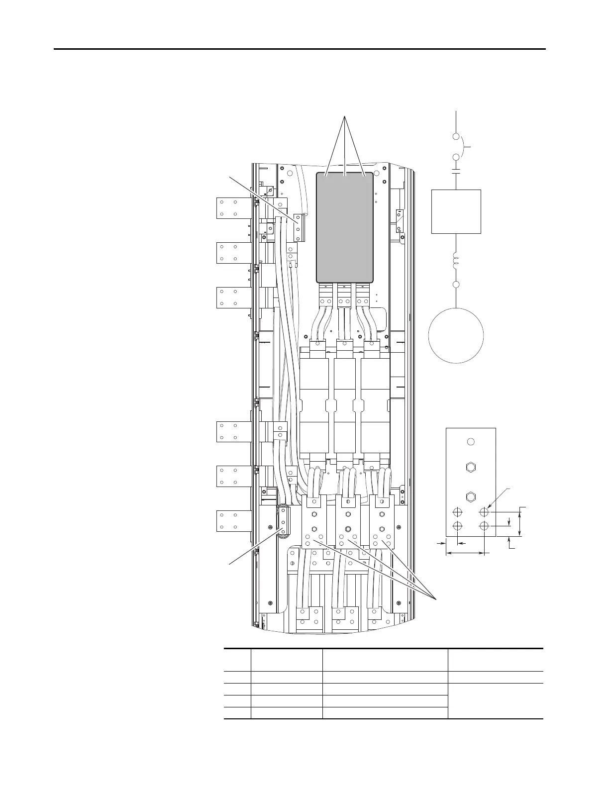
Figure 113 - Option P3 or P5 Disconnect, Option P11 Input Contactor, and Option L2 or L4
Output Reactor (only floor mount Frame 8)
ø15 (0.6)
4 Places
44.5
(1.75)
19.1
(0.75)
70.5
(2.80)
21.5
(0.85)
1
2
3
4
Drive
Motor
P3 or P5
P11
L2 or L4
Output Terminal
No. Name Description Recommended Torque
N•m (lb•in)
1 R/L1, S/L2, T/L3 Three-phase input power connection. Factory installed
2 PE Three-phase input ground.
38.0 (336)3 PE Three-phase motor ground.
4 U/T1, V/T2, W/T3 Motor connection.

Table of Contents

Other manuals for Allen-Bradley 20F

Questions and Answers:

Question and Answer IconNeed help?

Do you have a question about the Allen-Bradley 20F and is the answer not in the manual?

Allen-Bradley 20F Specifications

General IconGeneral
BrandAllen-Bradley
Model20F
CategoryController
LanguageEnglish

Related product manuals