268 Rockwell Automation Publication 750-IN001P-EN-P - April 2017
Chapter 5 I/O Wiring
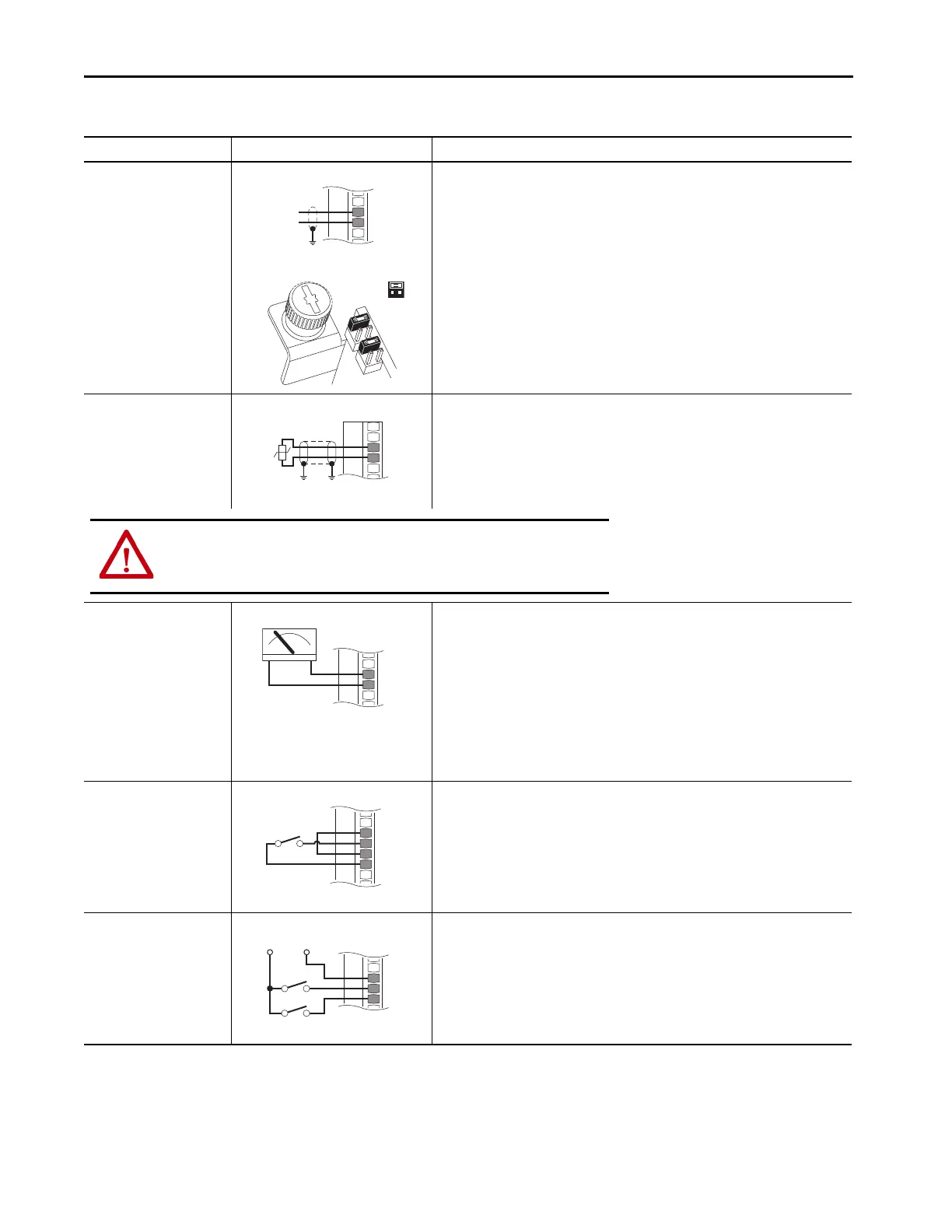
Analog Current Input
Unipolar Speed Reference
0…20 mA Input
22-Series I/O Module TB1
• Set direction mode
Port 0: P308 [Direction Mode] = 0 “Unipolar”
•Set selection
Port 0: P545 [Spd Ref A Sel] = Port X (22-Series I/O Module): P50 [Anlg In0 Value]
• Adjust scalingAdjust scaling
Port X (22-Series I/O Module): P51 [Anlg In0 Hi] = 20 mA
Port X (22-Series I/O Module): P52 [Anlg In0 Lo] = 0 mA
Port 0: P547 [Spd Ref A AnlgHi] = 60 Hz
Port 0: P548 [Spd Ref A AnlgLo] = 0 Hz
•View results
Port X (22-Series I/O Module): P50 [Anlg In0 Value]
Port 0: P592 [Selected Spd Ref]
HW Input PTC
Standard = DIN 44082
PTC Nominal = 1.8 kΩ
PTC Trip = 3.1 kΩ
PTC Reset = 2.2 kΩ
Short Circuit Trip = 80 Ω
22-Series I/O Module TB1
•Configuration
Port X (22-Series I/O Module): P40 [PTC Cfg] = 0 “Ignore,” 1 “Alarm,” 2 “Flt Minor,”
3 “Flt CoastStop,” 4 “Flt RampStop,” or 5 “Flt CL Stop”
•View results
Port X (22-Series I/O Module): P41 [PTC Sts]
Port X (22-Series I/O Module): P42 [PTC Raw Value]
Analog Voltage Output
±10V, 0…20 mA Bipolar
+10V Unipolar
22-Series I/O Module TB1
•Configuration
Port X (22-Series I/O Module): P70 [Anlg Out Type], bit 0 = 0
•Set selection
Port X (22-Series I/O Module): P75 [Anlg Out0 Sel] = Port 0: P3 [Mtr Vel Fdbk]
•Adjust scaling
Port X (22-Series I/O Module): P78 [Anlg Out0 DataHi] = 60 Hz
Port X (22-Series I/O Module): P79 [Anlg Out0 DataLo] = 0 Hz
Port X (22-Series I/O Module): P80 [Anlg Out0 Hi] =10V/20 mA
Port X (22-Series I/O Module): P81 [Anlg Out0 Lo] = 0V/0 mA
•View results
Port X (22-Series I/O Module): P77 [Anlg Out0 Data]
Port X (22-Series I/O Module): P82 [Anlg Out0 Val]
2-Wire Control Non-
reversing
24V DC internal supply
22-Series I/O Module TB1
• Set direction mode
Port 0: P308 [Direction Mode] = 2 “Rev Disable”
•Set selection
Port 0: P163 [DI Run] = Port X (22-Series I/O Module): P1 [Dig In Sts], bit 0 = Input 0
•View results
Port X (22-Series I/O Module): P1 [Dig In Sts]
Port 0: P935 [Drive Status 1]
2-Wire Control Reversing
External 24V supply
20-750-2262C-2R
20-750-2263C-1R2T
22-Series I/O Module TB1
• Set direction mode
Port 0: P308 [Direction Mode] = 0 “Unipolar”
•Set selection
Port 0: P164 [DI Run Forward] = Port X (22-Series I/O Module): P1 [Dig In Sts], bit 0 = Input 0
Port 0: P165 [DI Run Reverse] = Port X (22-Series I/O Module): P1 [Dig In Sts], bit 1 = Input 1
•View results
Port X (22-Series I/O Module): P1 [Dig In Sts]
Port 0: P935 [Drive Status 1]
Table 82 - 22-Series I/O Option Module TB1 Wiring Examples (Continued)
Input/Output Connection Example Required Parameter Changes
Ai0–
Ai0+
Common
+
1.8k
PTC
Ptc–
Ptc+
ATTENTION: To avoid an electric shock hazard, the connection of the motor
temperature sensor requires double or reinforced insulation between motor live
parts and the PTC.
Di C
Di 0
Di 1
+24V Common
Run Fwd
Run Rev
 Loading...

