Rockwell Automation Publication 750-IN001P-EN-P - April 2017 269
I/O Wiring Chapter 5
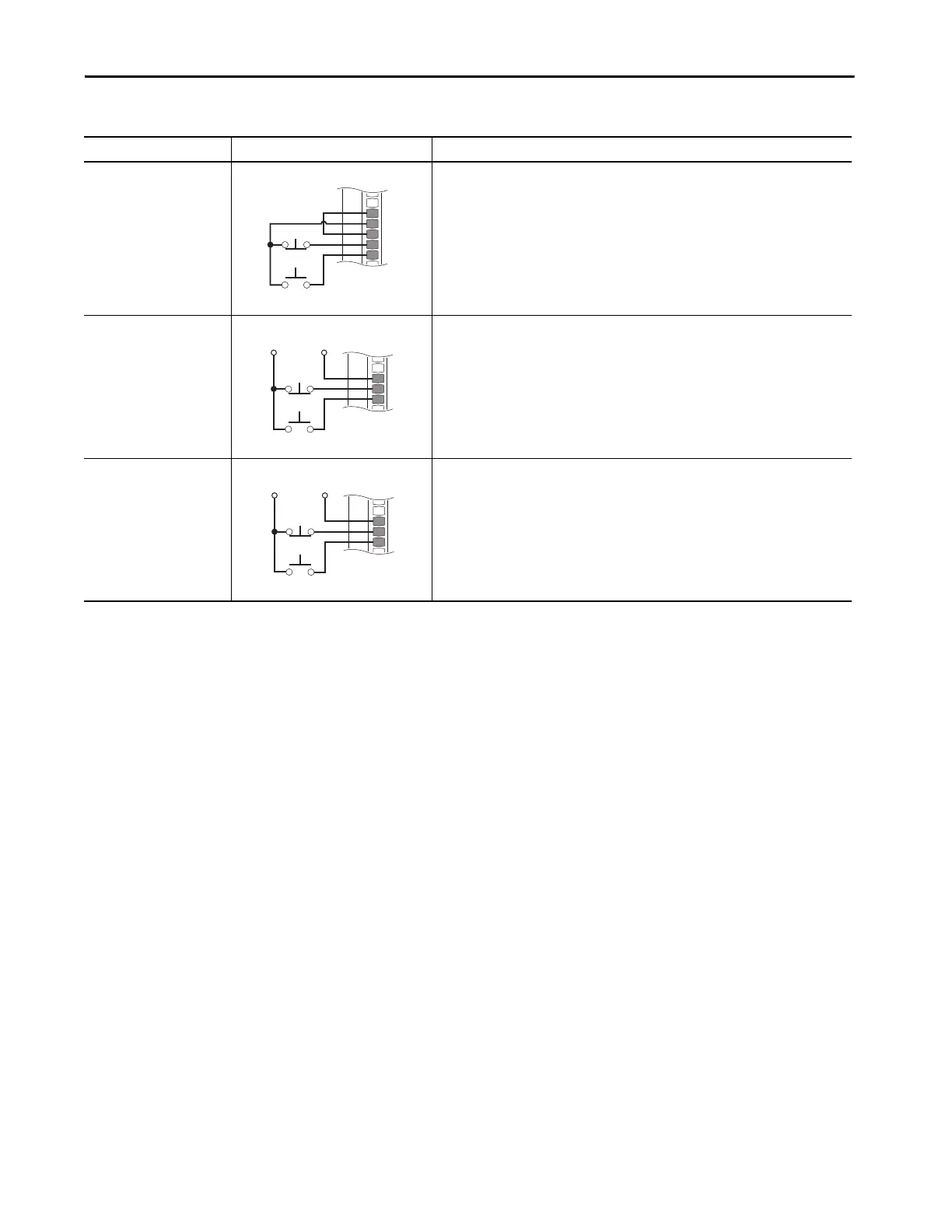
3-Wire Control
Internal supply
22-Series I/O Module TB1
•Set selection
Port 0: P158 [DI Stop] = Port X (22-Series I/O Module): P1 [Dig In Sts], bit 0 = Input 0
Port 0: P161 [DI Start] = Port X (22-Series I/O Module): P1 [Dig In Sts], bit 1 = Input 1
•View results
Port X (22-Series I/O Module): P1 [Dig In Sts]
Port 0: P935 [Drive Status 1]
3-Wire Control
External 24V supply
20-750-2262C-2R
20-750-2263C-1R2T
22-Series I/O Module TB1
•Set selection
Port 0: P158 [DI Stop] = Port X (22-Series I/O Module): P1 [Dig In Sts], bit 0 = Input 0
Port 0: P161 [DI Start] = Port X (22-Series I/O Module): P1 [Dig In Sts], bit 1 = Input 1
•View results
Port X (22-Series I/O Module): P1 [Dig In Sts]
Port 0: P935 [Drive Status 1]
3-Wire Control
External 120V supply
20-750-2262D-2R
22-Series I/O Module TB1
•Set selection
Port 0: P158 [DI Stop] = Port X (22-Series I/O Module): P1 [Dig In Sts], bit 0 = Input 0
Port 0: P161 [DI Start] = Port X (22-Series I/O Module): P1 [Dig In Sts], bit 1 = Input 1
•View results
Port X (22-Series I/O Module): P1 [Dig In Sts]
Port 0: P935 [Drive Status 1]
Table 82 - 22-Series I/O Option Module TB1 Wiring Examples (Continued)
Input/Output Connection Example Required Parameter Changes
24VC
+24V
Di C
Di 0
Di 1
Stop
Start
Di C
Di 0
Di 1
Stop
Start
+24V Common
Di C
Di 0
Di 1
Stop
Start
+120V Common
 Loading...

