270 Rockwell Automation Publication 750-IN001P-EN-P - April 2017
Chapter 5 I/O Wiring
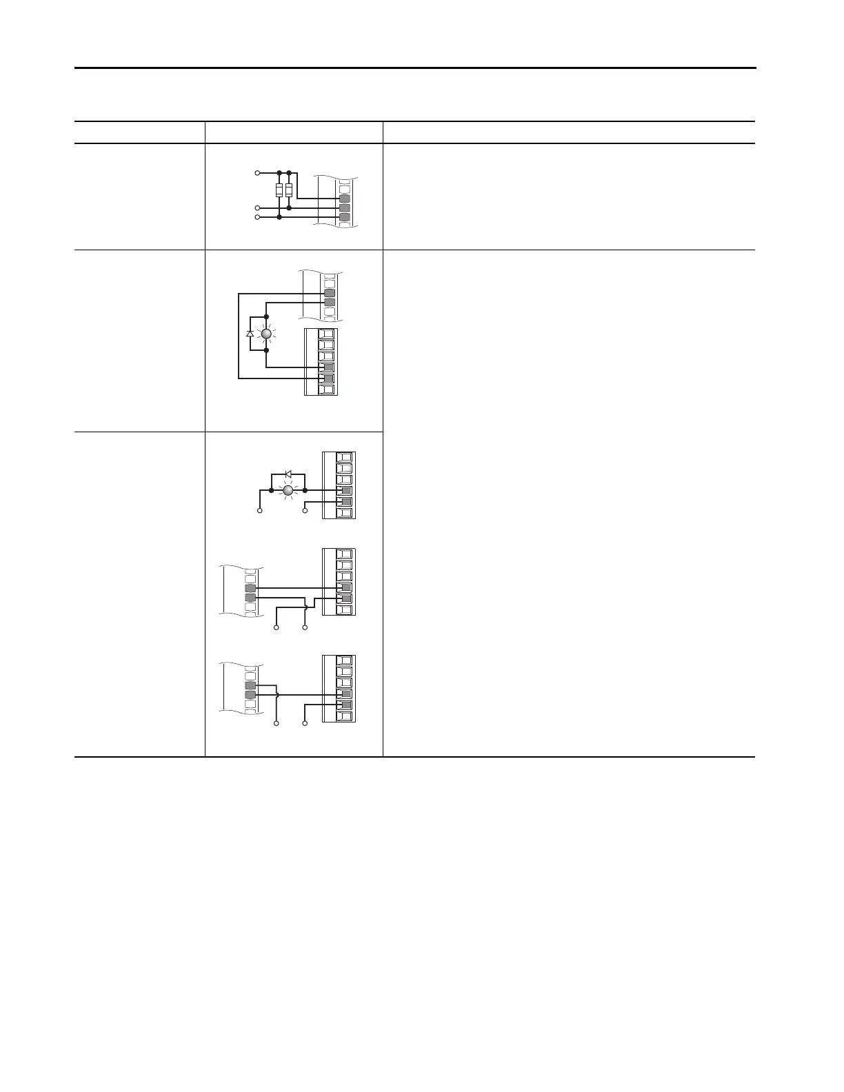
Digital Input
PLC Output Module
22-Series I/O Module TB1
•Set selection
Port 0: P158 [DI Stop] = Port X (22-Series I/O Module): P1 [Dig In Sts], bit 0 = Input 0
Port 0: P161 [DI Start] = Port X (22-Series I/O Module): P1 [Dig In Sts], bit 1 = Input 1
•View results
Port X (22-Series I/O Module): P1 [Dig In Sts]
Port 0: P935 [Drive Status 1]
Digital Output
Internal supply
20-750-2263C-1R2T
22-Series I/O Module TB1
22-Series I/O Module TB2
•Set selection
Port X (22-Series I/O Module): P20 [TO0 Sel] = Port 0: P935 [Drive Status 1], bit 7 = Faulted
•View results
Port X (22-Series I/O Module): P5 [Dig Out Sts]
Digital Output
External supply
20-750-2263C-1R2T
PLC TB 22-Series I/O Module TB2
Table 82 - 22-Series I/O Option Module TB1 Wiring Examples (Continued)
Input/Output Connection Example Required Parameter Changes
DiC
Di0
Di1
Neutral/
Common
Control from
Prog. Controller
10k Ohm, 2 Watt
24VC
+24V
T0
TC
T1
T0
TC
T1
+24V Common
T0
TC
T1
T0
TC
T1
OR
+24VDC Common
PLC
1756-1B16
IN-0
GND-0
+24VDC Common
PLC
1756-1V16
OR
DC-0+
IN-0
 Loading...

