EasyManuals Logo
Home>Allen-Bradley>Controller>20F

Allen-Bradley 20F Installation Instructions

Allen-Bradley 20F
320 pages
To Next Page IconTo Next Page
To Previous Page IconTo Previous Page
Page #29 background imageLoading...
Page #29 background image
Rockwell Automation Publication 750-IN001P-EN-P - April 2017 29
Prepare for Installation Chapter 2
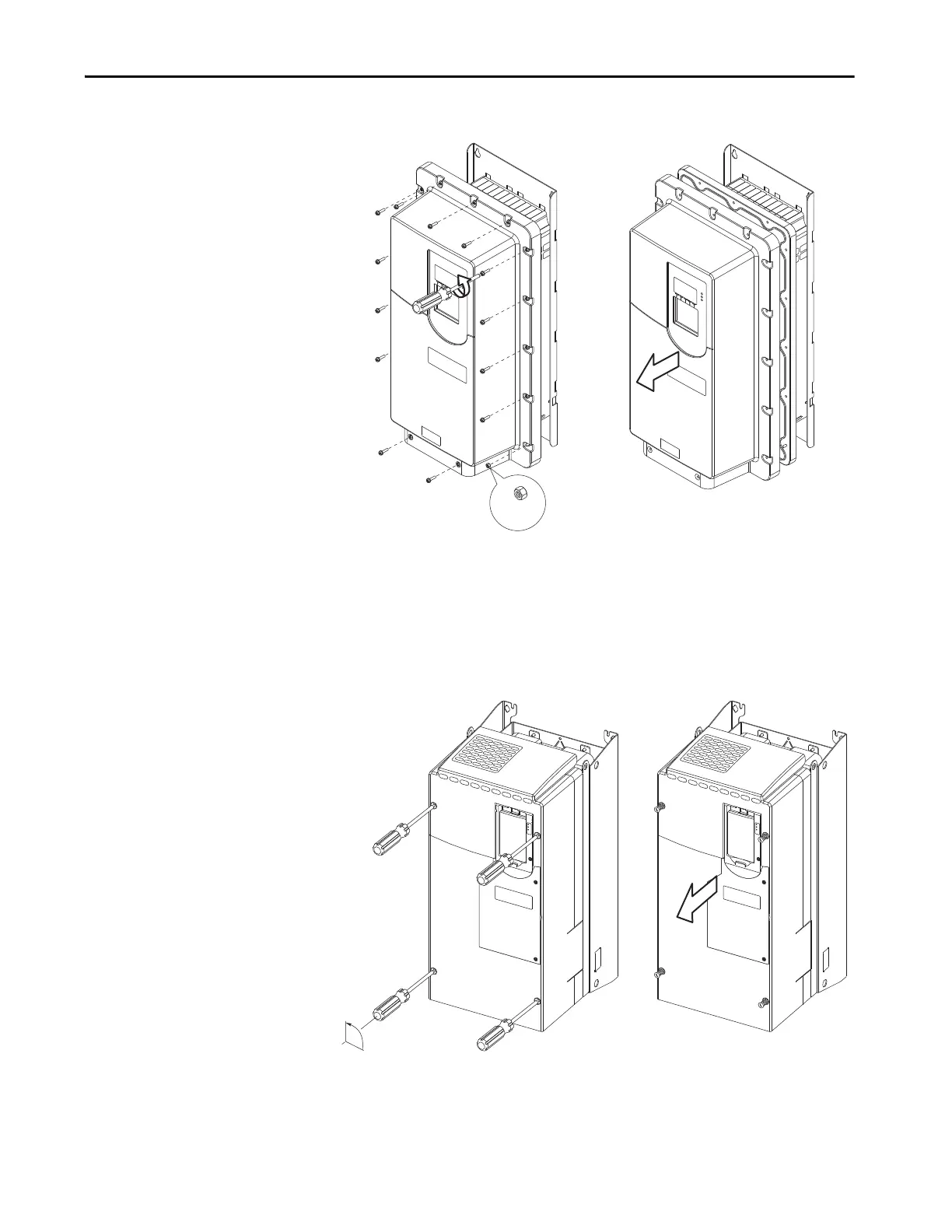
Figure 3 - Enclosure Code G (IP54, NEMA/UL Type 12) Wall Mount, Frames 2…5
To remove or replace the cover, use these tools and torque:
Recommended torque (screws and nuts) = 0.68 N•m (6.0 lb•in)
Recommended screwdriver = 6.4 mm (0.25 in.) flat or T20 Hexalobular
Recommended hex socket = 7 mm
Figure 4 - Enclosure Code N (IP00, NEMA/UL Open Type) Wall Mount, Frames 6 and 7
To remove or replace the cover, use this tool:
Recommended screwdriver = 9.5 mm (0.375 in.) flat
2x:
M4 X 0.7
90°

Table of Contents

Other manuals for Allen-Bradley 20F

Questions and Answers:

Question and Answer IconNeed help?

Do you have a question about the Allen-Bradley 20F and is the answer not in the manual?

Allen-Bradley 20F Specifications

General IconGeneral
BrandAllen-Bradley
Model20F
CategoryController
LanguageEnglish

Related product manuals