Rockwell Automation Publication 750-IN001P-EN-P - April 2017 59
Lift and Mount the Drive Chapter 3
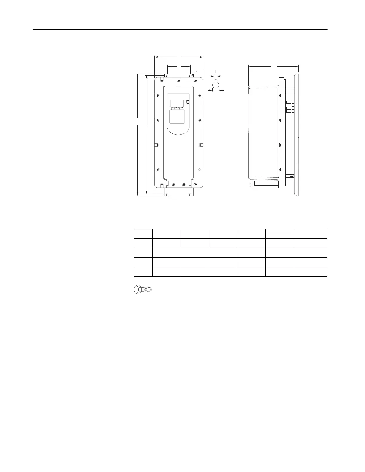
Figure 24 - IP54, NEMA/UL Type 12, Wall Mount Frames 2…5 (Frame 2 Shown)
Dimensions are in millimeters and (inches).
Weights are in kilograms and (pounds).
M6 (#10 or #12) mounting hardware recommended.
Frame A B C D E Weight, kg (lb)
2 215.3 (8.48) 543.2 (21.39) 222.2 (8.75) 100.0 (3.94) 528.2 (20.80) 7.8 (17.2)
3 268.0 (10.55) 551.0 (21.69) 220.1 (8.67) 158.0 (6.22) 533.0 (20.98) 11.8 (26.1)
4 300.0 (11.81) 571.0 (22.48) 220.1 (8.67) 194.0 (7.64) 553.0 (21.77) 13.6 (30.0)
5 348.0 (13.70) 647.0 (25.47) 220.1 (8.67) 238.0 (9.37) 629.0 (24.76) 20.4 (45.0)
A
C
E
B
14.3 (0.56)
6.4 (0.25)
D
 Loading...

