66 Rockwell Automation Publication 750-IN001P-EN-P - April 2017
Chapter 3 Lift and Mount the Drive
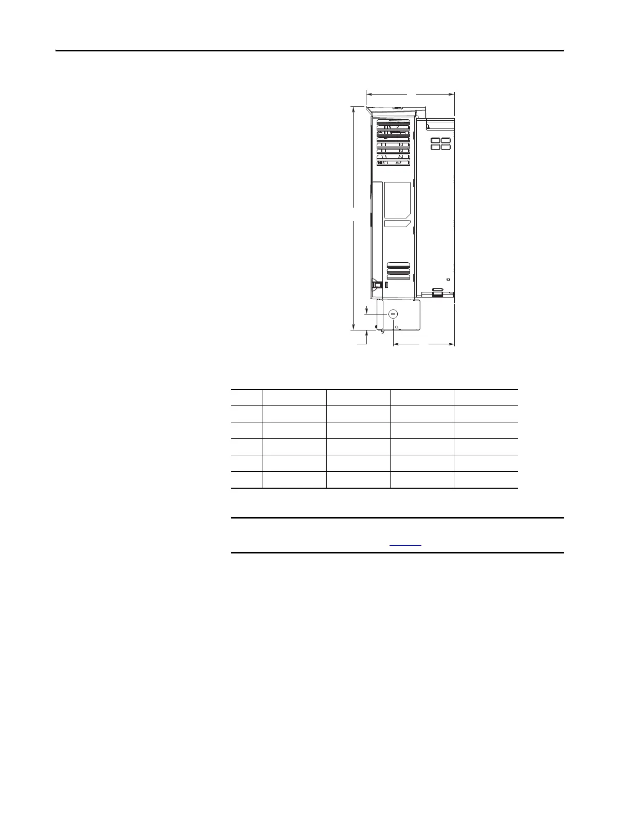
Figure 31 - NEMA/UL Type 1 Kit, Wall Mount Frames 1…5 (Frame 4 Shown)
Dimensions are in millimeters and (inches).
Frame A B C D
1 215.4 (8.48) 458.8 (18.06) – –
2 222.2 (8.75) 497.1 (19.57) 117.7 (4.63) 38.0 (1.50)
3 223.1 (8.78) 530.1 (20.87) 154.7 (6.09) 38.0 (1.50)
4 222.7 (8.77) 564.4 (22.22) 154.7 (6.09) 40.0 (1.57)
5 222.7 (8.77) 665.4 (26.20) 155.0 (6.10) 55.0 (2.17)
IMPORTANT NEMA Type 1 kits (catalog number 20-750-NEMA1-Fx) do not change the
mounting dimensions in Figure 23
(where x is the frame size of the drive)
B
A
CD
 Loading...

