86 Rockwell Automation Publication 750-IN001P-EN-P - April 2017
Chapter 3 Lift and Mount the Drive
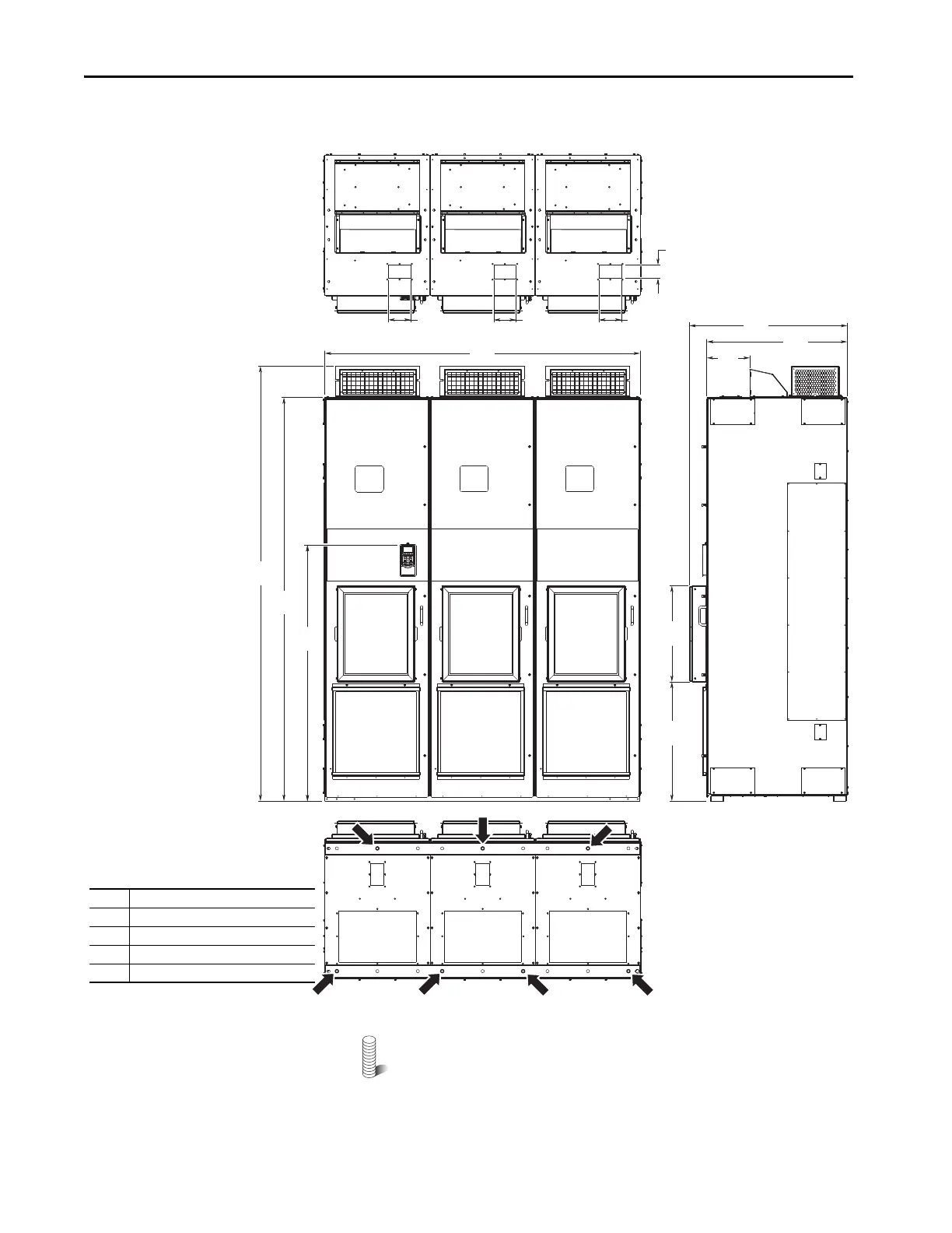
Figure 51 - IP54, NEMA 12, MCC Style Cabinet, Floor Mount Frame 10 (Enclosure Codes K and Y)
IP54, UL Type 12, MCC Style Cabinet, Floor Mount Frame 10 (Enclosure Code J)
M12 (1/2 in.) Property Class 8.8 anchor hardware is recommended
to fasten the drive cabinet through its internal mounting angle to the
foundation. Anchor bolts can be pre-located and embedded in the
foundation before instillation.
800
(31.5)
898
(35.4)
240
(9.4)
680
(26.8)
547
(21.5)
2477
(97.5)
2300
(90.6)
1464
(57.6)
127
(5.0)
76
(3.0)
11
1
1
1
1
3
4
4
4
2
127
(5.0)
127
(5.0)
1800
(70.9)
No. Description
1 Control wiring conduit plates.
2Optional HIM.
3 Recommended seven-hole anchoring.
4Power wiring conduit plates.
Bottom
To p
 Loading...

