EasyManuals Logo
Home>Allen-Bradley>Controller>20F

Allen-Bradley 20F Installation Instructions

Allen-Bradley 20F
320 pages
To Next Page IconTo Next Page
To Previous Page IconTo Previous Page
Page #85 background imageLoading...
Page #85 background image
Rockwell Automation Publication 750-IN001P-EN-P - April 2017 85
Lift and Mount the Drive Chapter 3
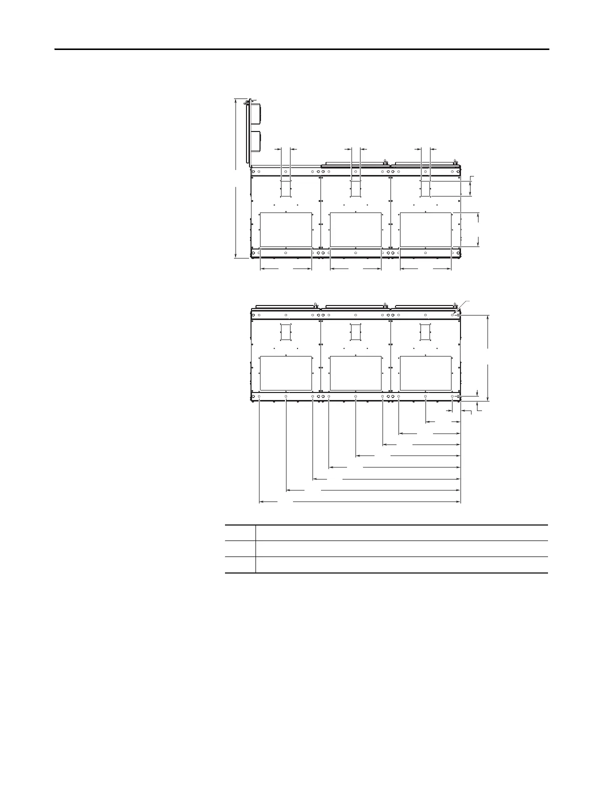
Figure 50 - IP20, NEMA/UL Type 1, MCC Style Cabinet, Floor Mount Frame 10 Bottom Access
(Enclosure Codes L, P, W)
No. Description
1 Power wiring conduit plates.
2 Control wiring conduit plates.
1374
(54.1)
440
(17.3)
440
(17.3)
300
(11.8)
531
(20.9)
669
(26.3)
ø18.0
(0.71)
742
(29.2)
43
(1.7)
69
(2.7)
76
(3.0)
900
(35.4)
1131
(44.5)
292
(11.5)
440
(17.3)
76
(3.0)
1
1
1
2
2
2
1500
(59.1)
1731
(68.1)
1269
(50.1)
76
(3.0)
127
(5.0)

Table of Contents

Other manuals for Allen-Bradley 20F

Questions and Answers:

Question and Answer IconNeed help?

Do you have a question about the Allen-Bradley 20F and is the answer not in the manual?

Allen-Bradley 20F Specifications

General IconGeneral
BrandAllen-Bradley
Model20F
CategoryController
LanguageEnglish

Related product manuals