Section 7 Inspection Software
7-8
7.5.4 Device Connection Check (Measurement System Setup Diagram
Display) Screen
This program displays the setup diagram of the entire measurement system on a single
common screen.
The following section describes the name and gives a brief summary of the function of
each control effective on this screen.
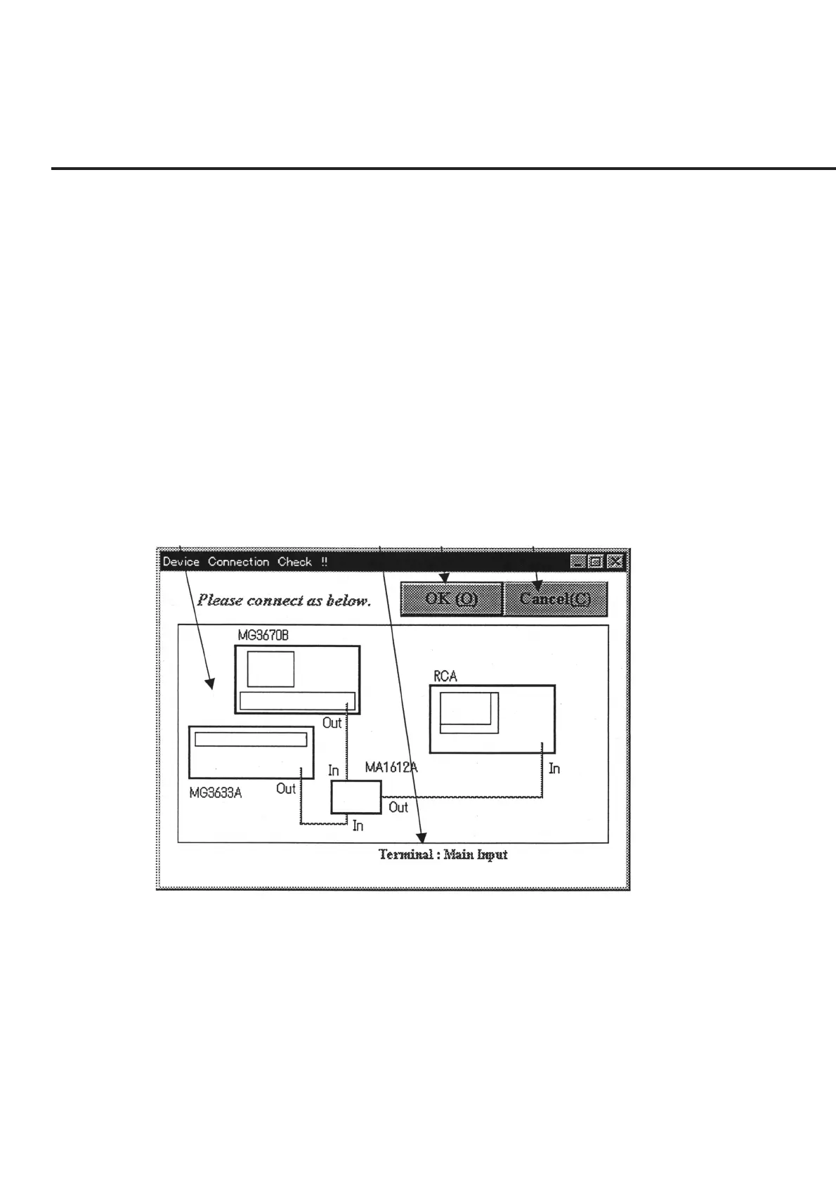
[1] Measurement system setup diagram display field
Displays the setup diagram of equipment used for each measurement field. (The 10
MHz reference signals and the GPIB cables are omitted.)
[2] Comment display field Displays supplementary explanations such as the I/O terminals etc. of the setup dia-
gram displayed in item [1].
[3] “OK” button Starts the measurement currently selected.
[1]
[2] [3] [4]
Fig. 7-4 Measurement System Setup Diagram Display Screen
[4] “Cancel” button Forcibly terminates the currently selected measurement. When this screen is termi-
nated, a message box is displayed prompting the confirmation of whether or not to
perform the measurements for the remaining selected measurement items.