Section 7 Inspection Software
7-28
7.6.4 Setting Reference and 100 MHz Calibration Factor
The “100 MHz Calibration Factor Data Input Screen” shown in Fig. 7-7 is displayed
when the prior calibration of the signal generator is performed for the measurement of
reference level accuracy of the spectrum analyzer.
Follow the procedure described below to input the data.
(1) Enter the serial number of the power sensor to be used in item [1] “Serial Num-
ber” in Fig. 7-7. A maximum of eight alphanumeric characters can be inputted.
(2) If data for the serial number entered in paragraph (1) above are already registered,
the registered information is displayed in items [2] to [5] in Fig. 7-7.
On the other hand, if no relevant data are registered; the current date and time are
displayed in items [2] and [3]. In this case, “Reference Cal Factor” of item [4]
becomes the standby state for the data entry.
(3) Directly input the data to change the data displayed in the item [4] “Reference Cal
Factor” or to make a new entry.
(4) Similarly, enter the data into the item [5] “100 MHz Cal Factor” in Fig. 7-7.
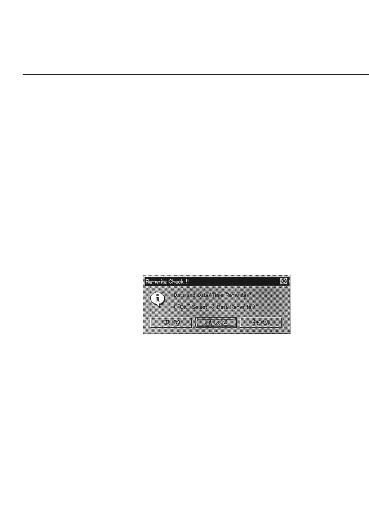
(5) Check each the set item, and click the item [6] “OK” button in Fig. 7-7. A mes-
sage prompting the confirmation of whether to save the information, as shown in
Fig. 7-19, is displayed regardless of whether changes were made to the data.
The buttons in this message box perform the following processing.
Fig. 7-19 Message Prompting Confirmation for Saving Changed Information
“Yes (Y)” ............ Saves the information displayed in items [4] and [5] together
with the current date and time information in Fig. 7-7.
“No (N)” ............. Although the initial file is not updated, the changes to the in-
formation are applied until this program comes to an end.
“Cancel” .............. Restores the screen back to the “100 MHz Calibration Factor
Data Input Screen” in Fig. 7-7.