6-25
6.6 Operation
6.6.9 Displaying Connection Confirmation Message
This program displays the cable connection diagram on the screen as shown in Fig. 6-
21 by using a bit map file. The following section shows the names of control function
on this screen as well as an outline of these functions.
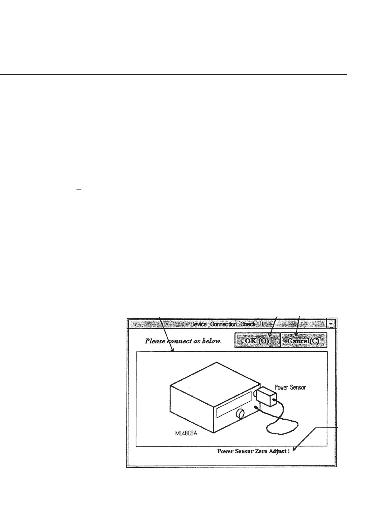
[1] Connection diagram display section
The program reads the connection diagram stored in the bit map file when this screen is
displayed and displays the diagram on the screen.
[2] OK (O) (“OK” button) Use this button after the connection displayed in section [1] is completed. When this
button is selected, the measurement is resumed.
[3] Cancel (C) (“Cancel” button) This button cancels the measurement, causing the screen to return to the “Initial Menu
Screen” shown in Fig. 6-4.
[4] Message display section This section displays supplementary explanations of the connection diagram displayed
in section [1], the input terminal, the cable used and other supplementary details.
When a connection confirmation diagram is displayed on this screen, perform opera-
tions by following procedures set out below.
(1) Connect the DUT as shown by the figure displayed in section [1]. The informa-
tion on the cable connection pad, the connection terminal, and other details are
displayed in the message box of section [4].
(2) Click the “OK” button of section [2] when the connection is completed. This
causes the measurement to be resumed.
[1] [2] [3]
[4]
Fig. 6-21 Connection Confirmation Message Screen
(3) Click the “Cancel” button of section [3] to cancel the measurement and return to
the “Initial Menu Screen” shown in Fig. 6-4.