Section 6 Correction Software
6-4
6.5.2 Summary of Measurement Module
The following section provides an outline of each measurement system covered by this
program.
6.5.2.1 Correction of Transmitter
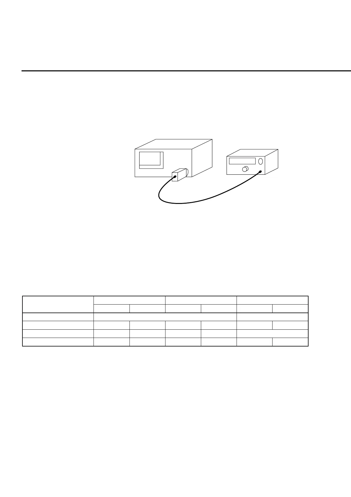
Test Device
ML4803A
In
Power Sensor
Out
Fig. 6-1 Connection Diagram of Measurement System of Transmitter
Read the output signal of the DUT from the power meter and calculate the correction
value. For measurement of the transmitter, when both the Main and Aux output termi-
nals are selected at the same time, a connection confirmation message is displayed at
the start of each measurement. The following section shows the connection diagram of
the measurement system and the list of set values for each DUT model.
Table 6-2 List of Set Values for Measurement of Transmitter
Measurement screen
Output level
Sensor used
Power meter range
MT8801B
Main Aux Main Aux Main Aux
–38 dBm
MA4602A
Range4
Tester Analog
–13 dBm
MA4601A
Range2
–28 dBm
MA4602A
Range5
–3 dBm
MA4601A
Range3
–23 dBm –3 dBm
MA4601A
Range1 Range3
MT8801B with OPT05 MT8802A