6-5
6.5 Software Summary
6.5.2.2 Correction of Receiver
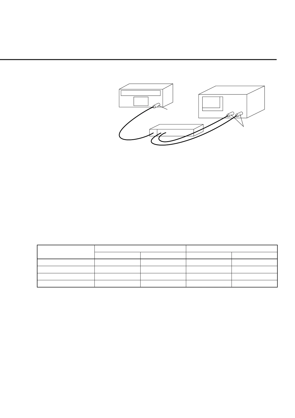
HP8665B
MT8802A
3 dB Pad
3 dB Pad
MN74A
Fig. 6-2 Connection Diagram of Measurement System of Receiver
Calibrate the output level of the signal generator registered via the channel selector by
the power meter, calculate the difference with the measured value of the DUT and set it
as the correction value. As the measurement of the receiver uses the channel selector,
switching in connection between Main and AUX does not take place. In addition,
continuous measurement of up to four units is enabled. The following section shows
the connection diagram of the measurement system and the list of measurement items
and set values for each DUT model. In the absence of a channel selector, using a 3 dB-
3 dB cable for direct connection enables measurement.
Table 6-3 List of Set Values for Measurement of Receiver
MS8606A
MS8607A
MT8801B
MT8802A
Main Input Aux Input
Power Meter
+7 dBm
+7 dBm
+7 dBm
+7 dBm
Spectrum Analyzer
–10 dBm
–10 dBm (*1)
–10 dBm
–10 dBm (*1)
Power Meter
--------
--------
--------
+7 dBm
Spectrum Analyzer
–20 dBm
–20 dBm (*1)
–20 dBm
–20 dBm (*1 )
*1: High Pass Filter switches ON and OFF.